Installation guidelines, Maintenance and troubleshooting, Adjustment and testing – Powers ETV400 Emergency Tempering Valves with Internal Cold Water Bypass User Manual
Page 2: Operation
1. Flush all piping thoroughly before installing.
2. The installation and field adjustment of ETV valves are the responsi-
bility of the installer and shall be carried out in accordance with the
following steps.
3. Locate ETV valve as close as possible to the fixture being supplied.
It shall be accessible for testing, adjustment and/or maintenance in
its installed position.
4. Shutoff valves are installed for maintenance purposes, provision
shall be made to prevent unauthorized shutoff.
5. When ETV valve supplies tempered water to self-closing and/or sole-
noid valves, provide a shock absorber (Powers' part # 460 353) on the
discharge line. This protects the ETV valve actuator from damage by
water shock waves generated by the quick closing valves.
6. Consult proper medical/safety authorities for the opti-
mum temperature for your application. Before use,
check for proper discharge temperature. Reset if neces-
sary. Valve is preset for 85°F (29°C)
Installation Guidelines
n
What to look for if:
• The flow of water is less then desired.
a. Stop valves or supply to HydroGuard
®
XP not fully open.
b. Clogged checkstop strainer screens.
c. Accumulation of lime deposit around valve seats.
d. Low supply pressure or unusual supply temperature.
• The flow of water is completely shutoff.
a. Stop valves or supply valves are completely closed.
b. Valves downstream from HydroGuard
®
XP are fully closed.
c. Loss of cold water supply pressure
Maintenance and Troubleshooting
n
1. Loosen adjustment locking screw
2. Check outlet temperature, which is factory set to 85°F (29°C). If it
is not, reset it by loosening adjustment locking screw and rotating
temperature adjustment screw clockwise to reduce temperature or
counterclockwise to increase the outlet temperature.
3. Close cold water checkstop. Verify that flow shuts down immedi-
ately.
4. Open cold water checkstop. Close hot water checkstop. Verify
adequate flow from fixture(s).
5. Open hot water checkstop, verify temperature returns to set tem-
perature.
6. Tighten adjustment locking screw.
7. Record test data on maintenance tag which should be provided by
the facility.
Contact Powers application department at 800.669.5430 for
high temperature readjustment procedure.
Adjustment and Testing
n
2
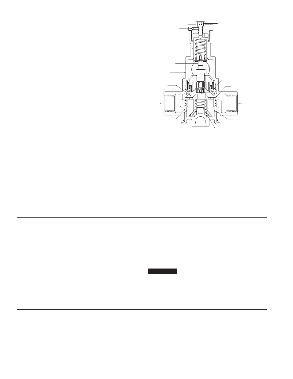
Body
Mixing
Chamber
Thermostatic
Actuator
Hot Water
Cold Water
Plunger
Temperature
Adjustment
Screw
Cold Water
Seat
Hot Water
Seat
Actuator Return
Spring
Outlet
By-Pass
Check
Overload
Assembly
Adjustment
Locking Screw
Hot and cold water supplies enter HydroGuard
®
XP at indicated ports
(See Fig. 1) then flow past plunger and seats. Next, hot and cold water
flow is directed to the mixing chamber where the thermostatic actuator
is located.
Temperature adjustment screw moves the actuator to determine the
discharge temperature. If discharge temperature rises due to inlet
pressure or temperature, the actuator expands, decreasing flow of hot
water. The reverse occurs with a drop in discharge temperature.
Cold water supply failure - causes actuator to expand forcing the plung-
er against the hot water seat.
In case of hot water failure cold water will flow through cold water
bypass to the outlet.
Figure 1
Operation
n
NOTICE