Powers ES150 Emergency Tempering Valves with Internal Cold Water Bypass User Manual
Page 3
3
Disassembly
1. Close supply valves and/or checkstops
2. Remove valve from its outlet piping. Work should be per-
formed on a clean table or workbench.
3. Remove bonnet screws, bonnet and actuator.
4. Loosen cartridge and remove.
5. Remove O-ring from the back of the cartridge.
Inspection
1. Inspect body for any damage, deposits or pitting. Clean or
replace as necessary.
2. Check the cartridge for any damage, deposit or pitting. Ensure
that the shuttle is free by placing the cartridge on a hard
surface and pressing on the shuttle with your thumb. Shuttle
should move smoothly approximately 1/8" with approximately
20 lbs. of force. Press on the bypass poppet with a ball point
pen or similar instrument to insure it moves smoothly and
freely. Poppet should move 1/16" with less then 1 lb. force. Do
not attempt to disassemble the cartridge. If any component
appears stuck, worn or damaged, replace the entire cartridge.
3. Check the actuator for proper operation at room temperature.
Hold actuator between your finger and thumb. Apply gentle
force on end of stem. Measure the entire length of the actua-
tor and then place it in the hot water (105-110°F) for 10 sec-
onds. Actuator stem should extend at least 1/8" longer than
when at room temperature.
Due to the safety nature of this product, we recom-
mend removal of the valve by a licensed contractor
and full inspection of all components whenever the
valve is disassembled for any reason.
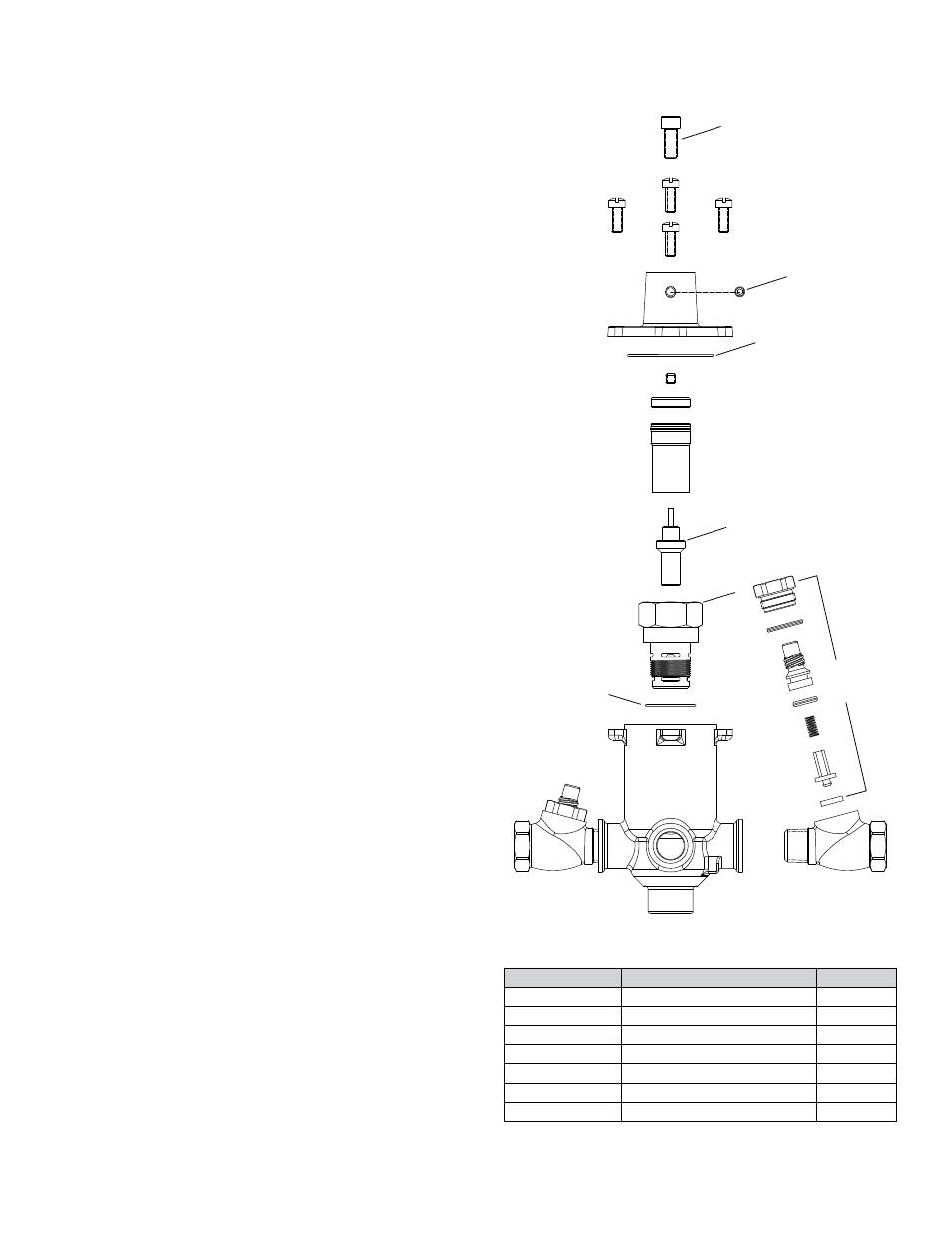
Disassembly and Inspection
n
Parts List
n
Index
Description
Part No.
1
Adjustment Screw
390 546
2
Adjustment Locking Screw
390 026
3, 4
Actuator Kit
390 579
3, 5
Cartridge Kit
390 580
3, 6, 13 (not shown)
Gasket & O'Ring Kit
390 581
7
Checkstop Rebuild Kit, RB
141 000
7
Checkstop Rebuild Kit, CP
141000A
1
2
3
4
5
6
7