Parts, Notice – Powers 744 Series Accritem Rigid and Remote Bulb Blind Controllers - Rigid Bulb User Manual
Page 4
4
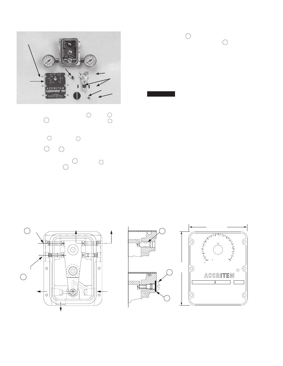
To reassemble:
1. Install new sensitive tube assembly
19
to body
1
.
2. Install lever
7
. Tighten the lever pivot screws
21
as
required. The lever must be in the exact center of the
body and must move freely but without side play.
3. Install screws
31
and gaskets
32
on water-operated
controller.
4. Install parts
8
and
9
. (Note relationship for direct
and reverse acting. See Figure 6.)
5. Back out adjustment screw
5
until collar
19
touches
the pivots on the lever
7
.
6. Install cover plate
2
.
7. Install adjustment knob with set screw
3
. The knob
indicator (white line on side of knob) should be opposite
the dial marking corresponding to the room temperature.
Tighten the knob set screw very firmly.
8. Turn the adjusting knob to the desired control temperature
for approximate calibration.
9. Recalibrate as required after the controller is installed and
connected to the supply and control lines.
NOTICE
On units with a date code of 3L48 and later: When replacing a
knob (744-036) or cover plate (744-170), a new knob (744-234)
and cover plate (744-170D) must be ordered.
Figure 7
B
(6 screws)
C
E
G
A
D
F
(2 pivots)
350
300
250
150
100
50
180
10
40
70
100
130
160
C
F
POWERS
PROCESS CONTROLS
Skokie, Il.
Mississauga, Ontario
PRODUCT NO.
DATE CODE
ACTION
R
21
21
21
31
32
Front View of Cover
Air Operated
Water Operated
Section “A–A”
*Used in Water-Operated Controllers Only
1/4" NPT to Drain (Water Operated Only)
1/8" NPT
Air Supply
1/8" NPT
Return
Reverse-Acting
Pivot
Direct-Acting
Pivot
A
A
19
18
17
10
11* 12
13
15
16
20
13 (1/2")
92
(3-5/8")
73 (2-7/8")
292 (11-1/2")
40 (1-19/32")
57 (2-1/4")
Reverse Acting Spring Location
8
Direct-Acting
Spring Location
9
Water Operated
30
17
18
2
6
3
7
1
4
5
9
8
Parts
n