Powers 744 Series Accritem Rigid and Remote Bulb Blind Controllers - Rigid Bulb User Manual
Page 2
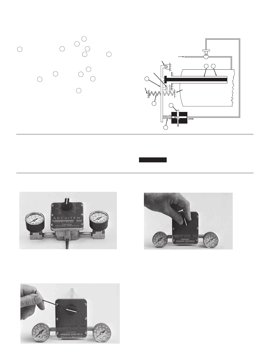
Direct Action Controller
A temperature change in the medium being controlled creates a
change in length of the sensitive tube
1
. An increase in tempera-
ture lengthens the sensitive tube
1
and moves the Invar rod
2
away from the lever
3
. The lever
3
, which pivots at Point
A, is moved to open the exhaust valve
4
by spring
5
. This
permits the supply (air or water) (S) to increase the pressure in the
control line (R) and close the normally-open valve. A decrease in
temperature shortens the sensitive tube
1
and moves the Invar
rod against the lever
3
. The lever
3
moves against the pres-
sure spring
5
, to open the exhaust valve
4
. This exhausts the
pressure in the control line and opens the valve.
The sensitivity adjustment screw
6
regulates the rate of flow
of the supply air (or water) to the controller to a change in tem-
perature. Turning the screw clockwise increases the sensitivity
by reducing the flow and increasing the response time. Turning
the screw counterclockwise decreases the sensitivity by
increasing the flow and reducing the response time.
Also see Figure 8 on page 7.
Figure 1
Operation Instructions
n
2
The sensitivity of the Accritem controller is adjusted by turn-
ing the restriction screw (Figure 2). (The restriction screw is
factory-set for air operation.) For water operation, the restriction
screw should be opened a minimum of 1/2 turn and controller
recalibrated. Restriction screw must never be fully closed. Make
Sensitivity
n
adjustments slowly, allowing about two (2) minutes after each
adjustment for the controller to balance.
Calibration
n
Set restriction screw for desired sensitivity. Air: 1/8 turn
from closed (minimum). Water: 1/2 turn from closed
(minimum).
Turn adjusting knob until 52 kPa (7-1/2 psi) control pres-
sure shows on gauge. Read temperature at bulb with
an accurate thermometer.
Loosen set screw and turn adjusting knob to indicate
temperature at bulb. Tighten set screw. Set controller for
desired control temperature.
Figure 2
Figure 3
Figure 4
Flowrite Valve
(Normally Open)
Exhaust Air
Tank
A
B
D
C
R
S
4
5
3
2
1
6
Positions “B” and “D” (dotted) show
pivot point (“B”) and spring when
controller is REVERSE acting.
Positions “A” and “C” (solid) show pivot
point (“A”) and spring when controller is
DIRECT acting.
NOTICE
If sensitivity is changed, controller must be recalibrated.