Powers 744 Series Accritem Rigid and Remote Bulb Blind Controllers - Remote Bulb User Manual
Page 3
TI TC744-2 Page 3
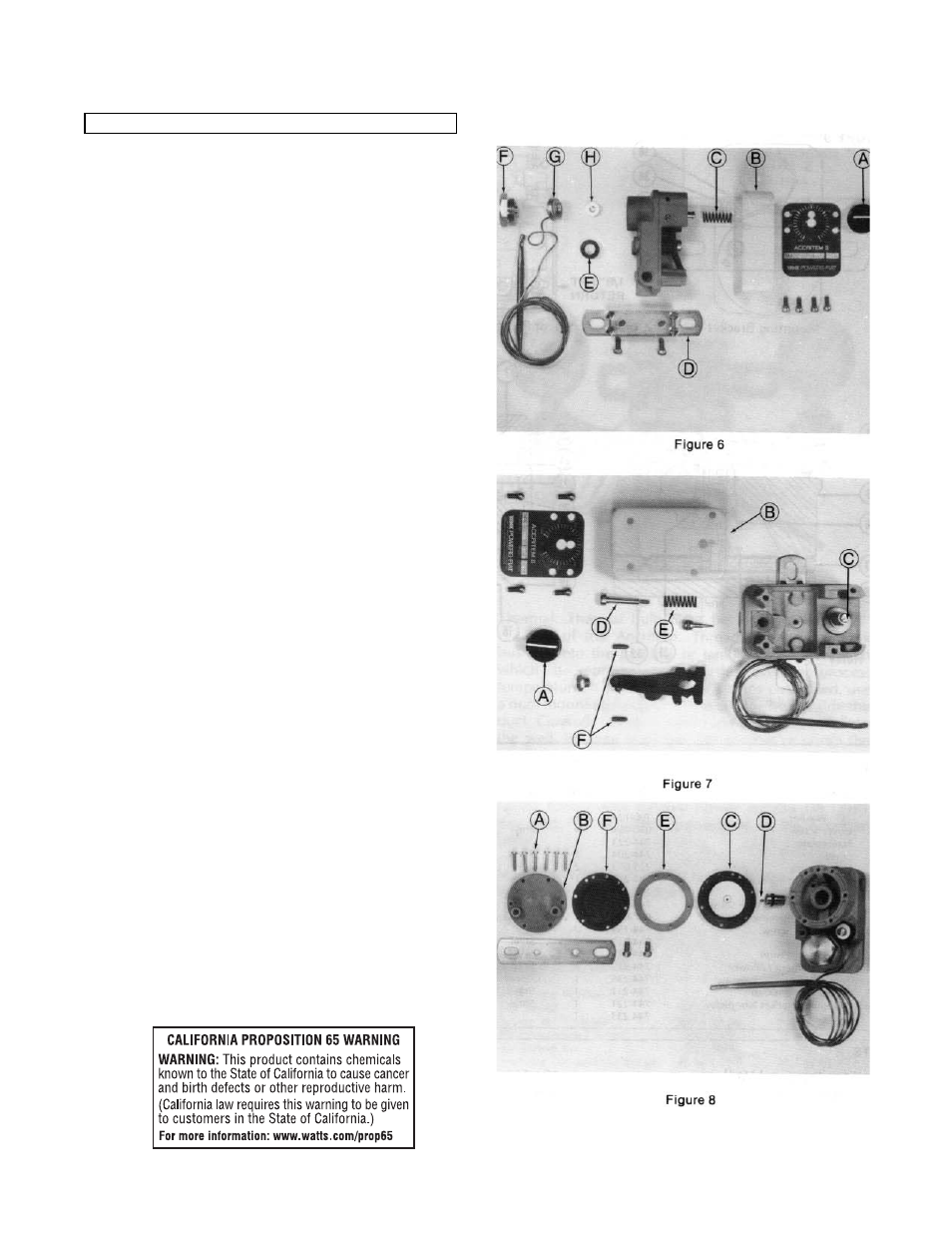
Disassemble (See Figure 6)
1. Loosen knob set screw and remove knob (A).
2. Remove cover (61, make sure not to lose valve spring (C).
3. Remove mounting bracket (D) and capillary tube washer (E).
4. Remove power element cap (F)
5. Remove sensing element (G).
Reassemble
1. Install new sensing element, make sure sensing element
follows (H) is in correct position.
2. Replace power element cap.
3. Carefully wrap capillary tubing around post one full turn
and replace tube holder washer and screw.
4. Replace valve spring, cover, and adjustment knob.
5. Recalibrate as required after the controller is installed and
connected to the supply and control lines.
To Change Controller Action (See Figure 7)
1. Turn adjustment knob counter-clockwise to remove tension.
2. Remove adjustment knob (A) and cover (B) be careful not
to loose valve spring (C).
3. Remove lever spring retainer (D) and spring (E).
4. Relocate lever pivot screws (F). See Figure 9 for location.
Screws should be snug, but not binding.
5. Replace lever spring and retainer, see Figure 9 for location.
6. Replace valve spring, cover, and adjustment knob.
7. Recalibrate.
Diaphragm Replacement for Relay Model Only
(See Figure 8)
1. Remove relay cover screws (A) and cover (B).
2. Remove both diaphragms and diaphragm spacer.
3. Replace inner diaphragm assembly (C). Make sure supply
valve ball (D) fits into exhaust valve cup and all holes of the
diaphragm align with holes in body.
4. Replace spacer (E) and outer diaphragm (F), again make
sure holes align.
5. Replace cover and screws. Be careful not to over
tighten screws.
CHANGE THERMAL SYSTEM