Powers 744 Series Accritem Rigid and Remote Bulb Blind Controllers - Remote Bulb User Manual
Page 2
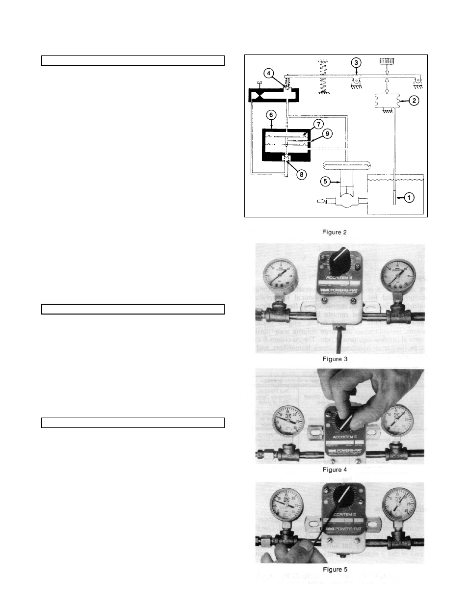
Non-Relay Model: Direct Acting (See Figure 2)
A temperature change in the control medium creates a
change in the liquid filled temperatures sensor (1) which
causes the bellows (2) to expand and push the lever arm (3).
The lever moves to close the exhaust valve (4). This permits
the supply air to increase the pressure in the control line and
close the normally open valve (5). A decrease in temperature
lowers the pressure within the bellows allowing the pressure
spring to push on the lever, opening the exhaust valve. This
lowers the pressure in the control line and opens the valve.
Relay Model:
In the relay equipped controllers, as the temperature increas-
es and the lever moves to close off the exhaust valve, the
restricted supply air moves through the control line to the
pilot relay (6). As the pressure increases in the upper air
chamber (7), the diaphragm assembly moves to open the
supply valves (8) thereby allowing a greater volume of supply
air through the control line to the valve (5).
A decrease in temperature causes the lever to open the
exhaust valve, venting air from the upper air chamber.
Diaphragm assembly assumes its normal position thereby
allowing the spring to close the supply valve. Control line
pressure is relieved through the exhaust port (9).
The sensitivity of the Accritem II is adjusted by turning the
restriction screw which is located on the bottom of the
controller, (see Figure 3). The Restriction screw must never
be tightly closed. Factory setting is about 1/4 turn open.
Turning the screw counter-clockwise decreases sensitivity,
reducing the response time. Make adjustments slowly, allow-
ing about two minutes after each adjustment for the con-
troller to balance.
NOTE: When sensitivity is changed, the controller dial and
knob should be re-calibrated.
The Accritem II must be calibrated to match the required out-
put pressure. For example: a valve with 3 to 13psi (21 to 90
kPa) range and a midpoint of 8psi (55 kPa) will require the
Accritem to pass 8psi (55 kPa) control pressure, (see Figure
4), when the knob points to a dial temperature that is the
same as the bulb temperature. To calibrate the instrument,
set the adjustment screw for desired sensitivity. Turn adjust-
ment knob on controller until required pressure shows on
control gauge and process temperature has enough time to
stabilize. Then take a recording of temperature at the bulb
location with an accurate thermometer. Loosen set screw
and turn adjusting knob to indicate temperature at bulb, (see
Figure 5). Tighten set screw. Set Controller for the desired
process temperature.
TI TC744-2 Page 2
OPERATION
SENSITIVITY ADJUSTMENT
DIAL CALIBRATION