Powers 595 Series 11 Self-Operating Temperature Regulators - Type ST Stainless Trim User Manual
Page 9
Testing the Thermal System
■
If the valve is not responding to temperature change, test the
thermal system.
1. Stop the fl ow of fl uid through the line.
2. DA: Raise the temperature of the bulb above the set point
temperature by placing it a container of hot water. This will
cause the plug to fully seat.
RA: Raise the temperature of the bulb above the set point
temperature by placing it a container of hot water. This will
cause the plug to fully open.
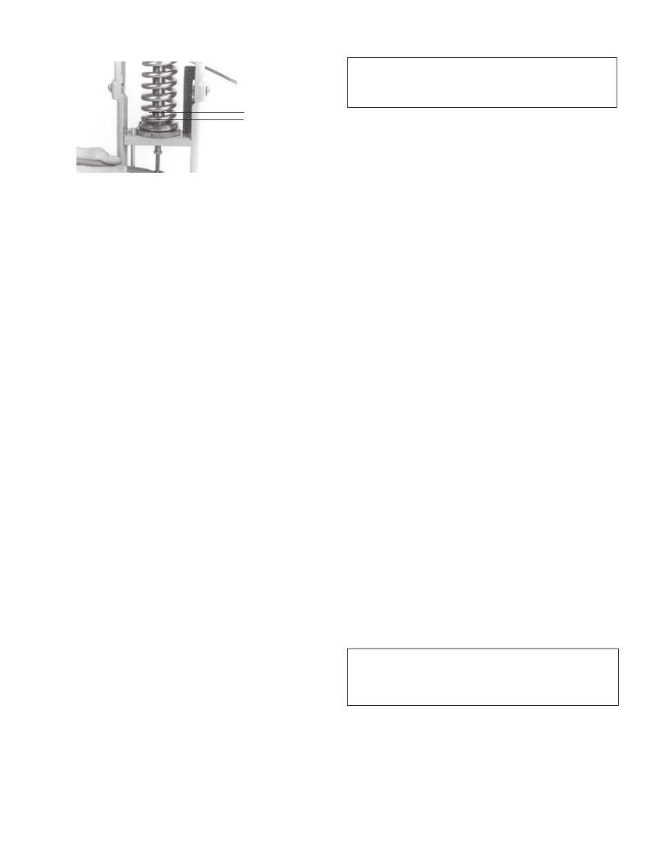
3.
Figure 14. With the valve plug seated, use a felt tip pen to
mark where the position of the packing gland assembly on
the stem.
4. DA: Place the bulb in a pan of cool water. Cool the bulb 30°F
(16°C) below set point so the valve is fully open.
RA: Place the bulb in a pan of cool water. Cool the bulb to or
beyond the set point so the valve plug is seated.
5. Use the pen to mark the new position of the packing gland
assembly on the stem.
6. The distance between the marks is the valve plug travel.
This should correspond with the Travel value in the Valve
Dimensions table on page 10. No movement or only partial
movement indicates the thermal system is defective and
should be replaced with a new system.
Preventive Maintenance
■
Once every three months, inspect the Regulator
as follows:
1. Visually check for leaks from the valve body joints, piping-to-
valve connections, packing and stem areas.
2. Visually check for excessive corrosion on the regulator,
including the bellows, capillary, bulb, thermal system legs,
bridge, and yoke. Also check for excessive corrosion on the
valve body.
3. Perform the instructions in Testing the Thermal System. Less
than full valve travel may indicate a leak in the bellows, capil-
lary, or bulb, or other problems. This may result in excessive
temperature in the process.
4. Test the temperature adjusting nut assembly for freedom of
movement (see Adjust Set Point for instructions).
5. Remove bulb from the process fl uid and check for excessive
corrosion, or erosion that may weaken the bulb and/or cause
thermal system failure.
Troubleshooting
■
• Erratic temperature control (valve cycles too hot/too cold)
1. Valve sized incorrectly. Verify valve selection.
2. Regulator is controlling at incorrect set point. Refer to Adjust
Set Point.
3. Bulb is poorly positioned and/or oriented, and will not control
the actual temperature of the heating/cooling medium. Refer
to Install Bulb.
4. Incorrect type of bulb is being used. See Table on page 11.
5. The valve stem is sticking. Lubricate the stem.
6. The valve stem is bent. Refer to Maintenance for disassembly
instructions and replace.
7. Packing gland assembly too tight. Loosen packing gland nut.
8. Faulty or incorrect steam traps. Replace with correct
steam trap.
9. Very wet steam. Install a high pressure steam trap just ahead
of the valve to drain off condensate that collects in the
steam line.
• Regulator does not shut off
1. Pressure differential is greater than allowable pressure drop.
Refer to Tables on pages 3 and 4.
2. Plug and/or seat is worn. Replace plug, seat or valve body
(refer to Maintenance).
3. Foreign material between the plug and the valve plug seat. Refer
to To replace the plug or seat ring for disassembly. Clean.
4. Bulb is poorly positioned and/or oriented, and will not control
the actual temperature of the heating/cooling medium. Refer
to Install Bulb.
5. Incorrect type of bulb is being used. See Table on page 11.
6. Valve sized incorrectly, causing wire drawing and leakage.
Refer to Water Capacities and Steam Capacities tables.
7. Packing gland assembly is too tight, locking valve stem.
Loosen packing gland assembly and lubricate if desired.
8. Bent valve stem; need to replace. Refer to Maintenance for
disassembly instructions.
9. Thermal system failure. Refer to Testing the Thermal System.
10. Temperature adjusting nut assembly raised too high. Refer to
Adjust Set Point.
• Valve chatters
1. Regulator installed with the fl ow of the control medium in
reverse of arrow direction on valve body.
2. Pressure differential too high, refer to Tables on pages 3
and 4 for correct pressure differential range.
3. Trapped condensate in line. Install a steam trap just ahead
of the regulator to drain off condensate that collects in the
steam line.
9
(Continued on page 16)
WARNING: Failure of the #11's thermal system will cause a heat-
ing valve to full open and a cooling valve to full close. If either of
these valve states results in an unsafe process condition, a high-limit
shutdown device, such as a Powers Aqua Sentry, should be used.
Distance between
two marks = Valve
Travel
14. Valve travel measurement
WARNING: Failure of the thermal system will result in a
constant rise in temperature (or constant high temperature)
of the fl uid which you are trying to control.