Powers 450 Piezo ESP HydroPanel II Sensor System for Single and Multiple Shower System Applications User Manual
Page 3
Installation cont.
n
3
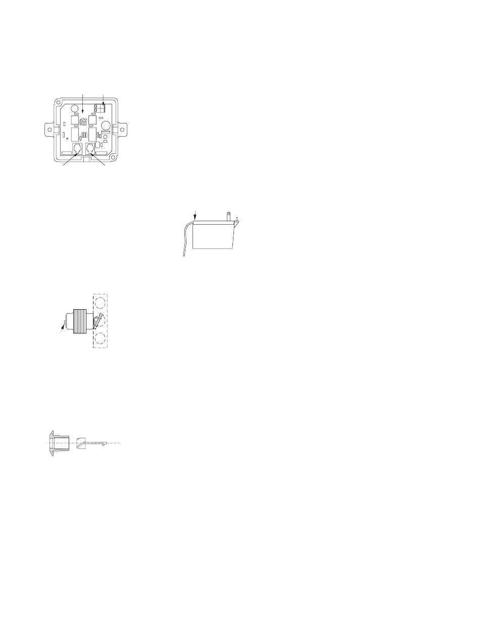
Push the two power supply wires (supplied with ESP kit)
through the hole in the side of the Control Box. Insert one wire
into each power connector and tighten each screw for a secure
connection. Replace the cover.
Install the Transformer
The plug-in and box mount
transformers can be positioned
in a chaseway, closet or ceil-
ing. Each can power up to eight
solenoids. For shower system
maintenance, a remote shutoff
switch can be installed.
WARNING: Do not supply
power to or plug in the trans-
former until all wiring is com-
plete.
Plug-In Transformer
The plug-in transformer will connect to a
110V AC wall outlet. Connect the two power
cord wires from the Control Box (or GCB) to
the screw terminals on the secondary side
of the transformer (Figure 6). Tighten the
screws.
NOTE: The wires can be lengthened with 22
gauge bell wire.
Box Mount Transformer
The box mount transformer will mount
on a 110V AC supply electrical junc-
tion box. The "J" box should be inside
the chase wall or above the ceiling.
Connect the power supply wires from
the Control Box (or GCB) to the sec-
ondary side of the transformer (Figure
7). Tighten the screws.
ESP System Test
Before attaching shrouding, the ESP system should be tested.
First, position and support the Hydropanel™ shrouding within
all cable limits (on a chair, etc.). Do not turn on power or water
supply yet.
Shower Applications
Insert the plugs from the proximity
sensor and the solenoid into their
labeled ports on the Control Box
(Figure 5). The unit will not operate
properly if the connectors are not in
their correct ports.
Supply power to the transformer, and activate the sensor by
pressing the pushbutton (Figure 8). The solenoid should make
an audible click.
ESP Shower Time Adjustments
NOTE: To prevent repeat cycling, the Piezo sensor has a five
second "lock-out" after the shower has been turned on or off.
During the five seconds, no matter how many times the push-
button is pressed, the sensor is programmed not to respond.
Also, the sensor is programmed to deactivate the shower if the
button is held in the active position (continuously invading the
proximity sensor's magnetic field).
Shower Applications
The ESP Control Box includes a potentiometer to set maximum
run-time, from 0 to 15 minutes (Factory setting is about 6 min-
utes). To adjust shower time, remove the cover of the Control
Box. Locate the slotted dial in the center of the circuit board
(Figure 5). With a small screwdriver, rotate the dial in small
increments, clockwise for more time, counterclockwise for less.
Turn dial carefully; overadjusting can damage the potentiom-
eter. After each adjustment, test and time the shower.
Re-Attach the Shrouding
The bottom bracket (Figure 4,D) will attach to the wall 25-1/2"
below showerhead height (see Figure 3). Use the bracket as a
template to mark positions for two mounting holes. Drill holes
and attach the bracket.
The chrome plated end cap (Figure 4) on top of the shrouding
has a section marked to be broken out for vertical and horizon-
tal piping clearance. To remove the marked piece, hit it sharply
with a hammer. Do not remove the entire end cap from the
shrouding.
Connect the outlet side of the solenoid to the showerhead pip-
ing by sliding the showerhead nipple (with the shrouding unit)
into the piping assembly. The bottom bracket will fit inside the
shrouding.
Before connecting shrouding with screws, turn on water supply
and activate the sensor to test the system. Water should flow
through showerhead. Press the pushbutton again to deactivate
the shower, then check all connections for leaks.
Use screws to attach the shrouding to the piping bracket and to
bottom mounting bracket (Figure 4, A and C).
1) When a bather presses the pushbutton, the sensor sends a
signal through the control box to the solenoid. The solenoid
opens and allows tempered water to flow to the shower-
head.
2) If the bather presses the pushbutton again, a signal is sent to
the solenoid to close and consequently shutoff the water.
3) If the bather does not press the pushbutton again, water will
automatically shutoff at the pre-set run-time. After shutoff,
the system is ready for the next user.
NOTE: To prevent repeat cycling, the proximity sensor has
a five second "lock-out" after the shower has been turned on
or off. During the five seconds, no matter how many times
the pushbutton is pressed, the sensor is programmed not to
respond. Also, the sensor is programmed to deactivate the
shower if the button is held in the active position (continuously
invading the proximity sensor's magnetic field).
Operation
n
SENSOR
SOLENOID
TIME ON
INC
REASE
Sensor Port
Solenoid Port
Power connections
Run-Time Potentiometer
attach wires
attach wires
Figure 5
Figure 6
Figure 7
Figure 8