Powers 450 Piezo ESP HydroPanel II Sensor System for Single and Multiple Shower System Applications User Manual
Page 2
2
Position the ESP Hydropanel™ II Unit
Determine the horizontal position of the unit according to
shower room layout, and mark the centerline (Figure 3). For mul-
tiple shower applications, the recommended minimum distance
between the centerline of two units is 36 inches.
Determine the floor-to-showerhead height for the unit.
Recommended heights are listed below:
Men
77" [1955.8mm]
Youth 66" [1676.4mm]
Women 70" [1778mm]
Youth 60" [1524mm]
Determine where the inlet piping will connect to the solenoid.
For the non-metallic solenoid, this connection is typically 1-1/2"
below showerhead height, and 2-1/4" left of centerline. For a
brass solenoid, it is 2-1/2" below showerhead height, and 2-1/4"
left of centerline.
Install the Solenoid and Piping Assembly
The piping and Hydropanel™ II shrouding come pre-assembled
(Figure 4). To detach, remove the screws at the showerhead (A)
and bottom bracket (C and C'). Slide the piping out of shrouding;
the showerhead remains part of the shroud.
WARNING: Before installing solenoid, flush the pipes to
ensure supply water is free of grit and sand.
NOTE: A service stop can be installed directly upstream of the
solenoid to facilitate maintenance and repair.
The non-metallic solenoid has 3/4" NPT end connections, and a
straight through flow path to minimize pressure loss. Make sure
the manual override switch is in the "OFF" position, or else water
will flow regardless of sensor activity.
The brass solenoid has 1/2" NPT end
connections.
Connect the supply line to the sole-
noid. Use only thread sealant on male
threads. Do not use Teflon tape; it
will clog the solenoid valve. Connect
the inlet piping so water flows in the
direction of the arrow on the solenoid.
To mount the upper bracket of the
piping assembly, drill the holes at the
same height as the top of the shower-
head (B and B').
Install Control Box
The control box (Figure 5), with standard cables, can be posi-
tioned up to 4 feet from the pushbutton/proximity sensor assem-
bly and up to 2 feet from the solenoid valve. [Optional cable
extensions can extend these distances to 1000 feet from the
sensor assembly, and 300 feet from the solenoid valve.] Remove
the cover. Use the box as a template to mark positions on the
wall for two mounting screws. Drill holes and attach the box.
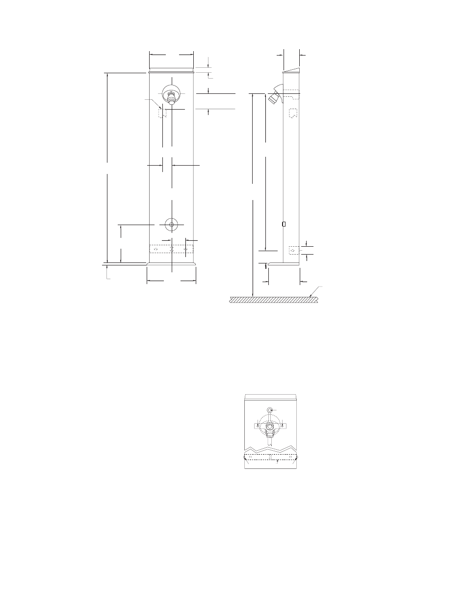
2
[50.8]
1-1/4
[31.8]
6
[154.4]
2-1/2
[63.5]
2-1/2
[63.5]
77
[1955.8]
4-3/4
[120.65]
FLOOR LINE
C for Hydropanel unit
L
7-1/2
[190.5]
7/16
[11.11]
30
[762.0]
7-3/32
[180.18]
11/16
[17.46]
SOLENOID INLET
1/2" NPT Brass
3/4" NPT Non Metallic
19-1/4
[488.95]
C for Solenoid
L
2-1/4
[57.15]
2.5 [63.5] Brass
1.5 [38.1] Non-Metallic
Front and Side Views - Dimensions of the ESP Hydropanel™ II Pushbutton Shower
Figure 3
A
B
B'
C
D
C'
End Cap
Figure 4
For Suggested
Showerhead
Heights see
Installation:
Positioning the
ESP Hydropanel™
II unit