E-flite F-4 Phantom 32 DF User Manual
Page 25
25
E-flite F-4 Phantom 32 DF Assembly Manual
Always use threadlock on metal-to-metal fasteners
to prevent them from vibrating loose.
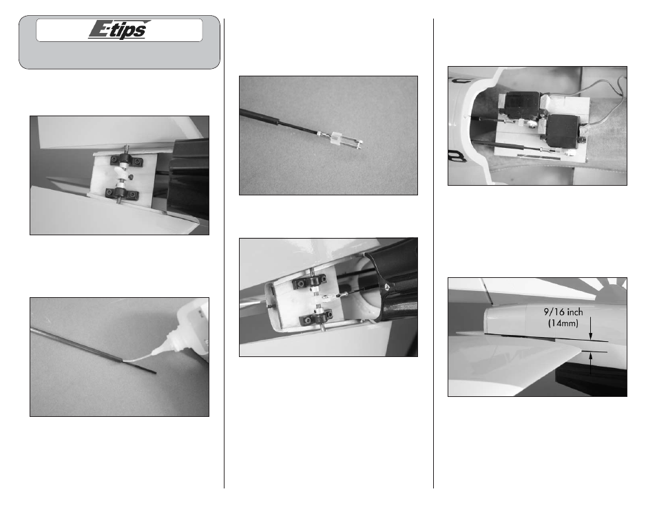
2. Secure the elevator mounting brackets to the
fuselage using four 3mm x 12mm socket head
screws and a 2.5mm hex wrench.
3. Center the carbon tube on the pushrod and
apply thin CA to the pushrod and carbon tube
to glue them together. Allow the CA to wick in
between the two for a secure bond.
4. Cut a piece of silicone tubing and slide it onto the
clevis. Thread a 2mm nut on the pushrod, then the
clevis to the pushrod. Prepare both ends of the pushrod
at this time. Make sure to use threadlock on the clevis
and nut to prevent them from vibrating loose.
5. Attach the clevis to the outer hole of the elevator
control arm.
6. Connect the clevis to the outer hole of the
elevator servo horn. Make sure to use threadlock
on the clevis and nut to prevent them from
vibrating loose.
7. With the radio on and the elevator servo
centered, adjust the length of the pushrod so the
distance from the tip of the elevator and the line
projected from the fuselage shown in the photo
below measures 9/16-inch (14mm). Use the hatch
line for a reference to project the reference line to
measure from.
8. Once the elevator position has been set, slide
the silicone keepers onto both clevises to keep the
clevises from opening accidentally.