Elevator installation – E-flite F-4 Phantom 32 DF User Manual
Page 24
24
E-flite F-4 Phantom 32 DF Assembly Manual
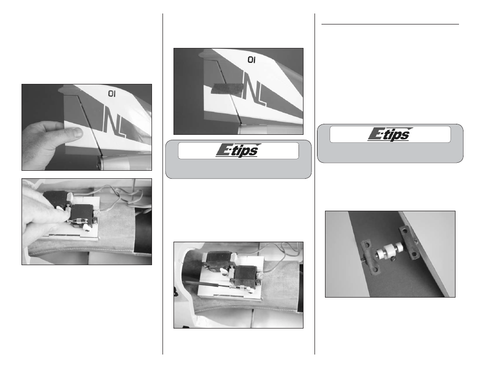
11. Fit the rudder to the fin while guiding the
pushrod into the fuselage. With the rudder tight
against the fin, check the length of the pushrod.
Adjust the pushrod length so it is close to aligning
with the rudder servo horn. Once adjusted, remove
the rudder and use needle nose pliers to tighten the
nut against the clevis at the rudder. Adjusting the
clevis at the rudder will be difficult once the rudder
has been hinged to the fin.
12. With the rudder removed, mix a small amount
of 5-minute epoxy. Apply the epoxy to the hinges
and in the holes in the fin. Position the rudder and
use low-tack tape to hold it while the epoxy cures.
Always use threadlock on metal-to-metal fasteners
to prevent them from vibrating loose.
13. Once the epoxy has cured, remove the tape
from the rudder. Use the radio to center the
rudder servo. Attach the clevis to the servo horn
on the inner hole and adjust the length of the
pushrod so the rudder is centered. Tighten the
2mm nut against the clevis, then slide the silicone
tubing over the clevis.
Elevator Installation
Required Parts
Fuselage assembly Transmitter
Receiver
Receiver battery
Metal clevis (2)
2mm nut (2)
Silicone tubing
3mm x 6mm socket head screw
Tail cone
Clear tape
3mm x 12mm socket head screw (4)
2mm x 290mm pushrod with 225mm carbon tube
Required Tools and Adhesives
Thin CA
Ruler
Threadlock
Hex wrench: 2.5mm
Always use threadlock on metal-to-metal fasteners
to prevent them from vibrating loose.
1. Secure the elevator control arm to the joiner
wire using a 3mm x 6mm socket head screw and a
2.5mm hex wrench. Make sure the arm is centered
between the collars and the screw is tightened on
the flat area of the elevator torque rod.