Rudder and elevator servo installation – E-flite F-4 Phantom 32 DF User Manual
Page 21
21
E-flite F-4 Phantom 32 DF Assembly Manual
15. Retract the landing gear using the radio
system. This will set the correct angle for the
landing gear door against the wing. Allow the glue
to cure overnight before moving the gear back to
the down position.
16. Repeat steps 2 through 15 to install the second
landing gear door.
Rudder and Elevator Servo Installation
Required Parts
Fuselage assembly Transmitter
Receiver
Receiver battery
Hardwood block, 15mm x 13mm x 6mm (4)
Servo with hardware (rudder and elevator)
Required Tools and Adhesives
Phillips screwdriver: #1
Pencil
Razor saw
Thin CA
5-minute epoxy
Mixing cup
Mixing stick
Drill
Drill bit: 5/64-inch (2mm)
Medium grit sandpaper
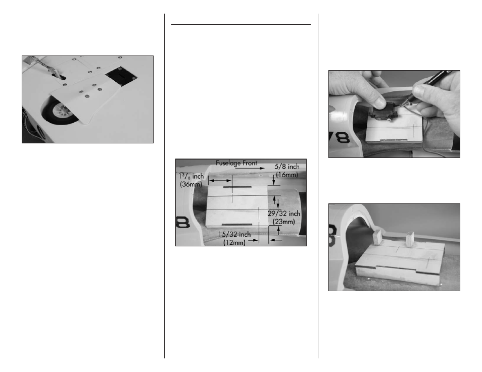
1. Use a pencil to mark the servo mounting plate in
the fuselage for the servo locations.
2. Prepare the elevator servo using the grommets
and eyelets included with the servo. Position the
servo so the bottom of the mounting tabs are
aligned with the line drawn on the plate. The servo
output will align with the line that is 1
3
/
8
-inch
(36mm) from the rear of the plate. Use a pencil to
mark the plate for the sides of the servo.
3. Prepare and epoxy the servo mounting
blocks as shown in the section “Aileron and
Flap Servo Installation.” Allow the epoxy to
fully cure before proceeding.