Main landing gear installation – E-flite F-4 Phantom 32 DF User Manual
Page 15
15
E-flite F-4 Phantom 32 DF Assembly Manual
12. Once the epoxy has cured, remove the wing
panel from the fuselage. Repeat steps 3 through 11
to install the remaining wing panel to the fuselage.
13. Once the epoxy has fully cured and both wing
panels have spars, remove any petroleum jelly
residue from the fuselage and wing using rubbing
alcohol and a paper towel.
Main Landing Gear Installation
Required Parts
Wing panel assembly (right and left)
Aluminum wheel collar with setscrew, 3.5mm (2)
Aluminum wheel spacer, 3.5mm (2)
Wheel, 1
7
/
8
-inch (48mm) (2)
Main landing gear strut (right and left)
3mm x 14mm countersunk self-tapping screw (8)
Required Parts (Fixed Gear Specific)
Main fixed landing gear unit (2)
Required Parts (Retract Specific)
Transmitter
Receiver
Receiver battery
Servo extension, 3-inch (76mm) (2)
Main landing gear retract (2)
Required Tools and Adhesives
Drill
Drill bit: 5/64-inch (2mm)
Threadlock
Hex wrench: 1.5mm
Thin CA
Phillips screwdriver: #1
Trim seal tool
Hobby knife with #11 blade
Low-tack tape
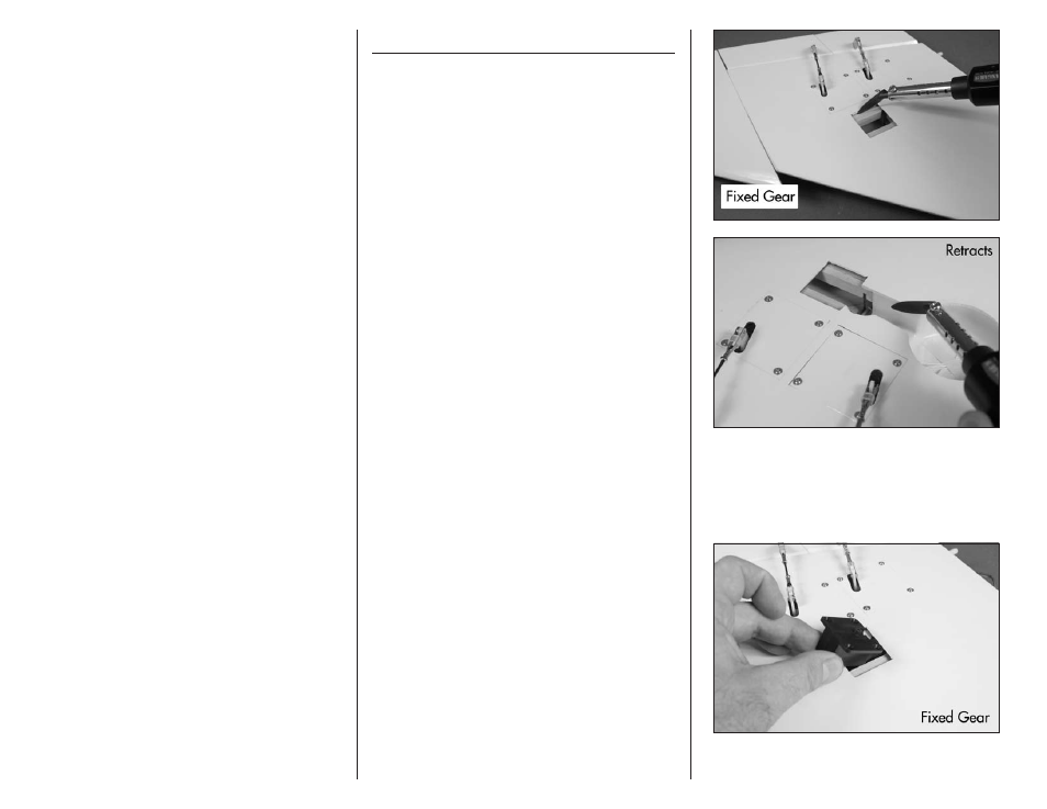
The installation of the retracts and fixed
gear follow the same procedure. The only
difference is the cutting of the covering and
the routing of the retract lead, which has been
highlighted in gray.
1. Use a hobby knife with a new #11 blade to
remove the covering to access the landing gear
mounts and wheel well if using the retracts. Leave
1/32-inch (1mm) of covering around the inside
edges. Use a trim seal tool to iron down the
covering around the edges to finish the opening.
2. Place a main landing gear block or retract
mechanism in the wing. The landing gear block
may distort the covering slightly during its
installation when installing the fixed gear. Make
sure it is resting flat on the landing gear rails.