Flap and aileron linkage installation – E-flite F-4 Phantom 32 DF User Manual
Page 11
11
E-flite F-4 Phantom 32 DF Assembly Manual
4. Use coarse grit sandpaper to lightly sand
the control horns where they fit into the openings in
the flap and aileron.
5. Repeat Steps 1 through 4 to prepare the
remaining aileron and flap control horns.
6. Use 5-minute epoxy to glue the control horn
into the holes for the aileron. Use a square to make
sure the control horn is perpendicular to the control
surface. Double-check the hole in the control horn
to ensure it is directly over the hinge line.
7. After around 3 minutes, before the epoxy
cures, carefully remove the tape from around the
control horns. Pull the tape away from the horn,
being careful not to disturb the position of the
control horn. This will allow the epoxy to flow out
slightly, leaving a fillet between the control horn
and control surface.
8. Repeat Steps 6 and 7 to install the remaining
aileron and flap control horn.
Flap and Aileron Linkage Installation
Required Parts
Wing panel (right and left)
Transmitter
Receiver
Receiver battery
Silicone tubing
Metal clevis (8)
2mm nut (6)
Threaded rod, 2mm x 25mm (2)
Threaded rod, 2mm x 40mm (2)
Required Tools and Adhesives
Ruler
Threadlock
Needle-nose pliers
Always use threadlock on metal-to-metal fasteners
to prevent them from vibrating loose.
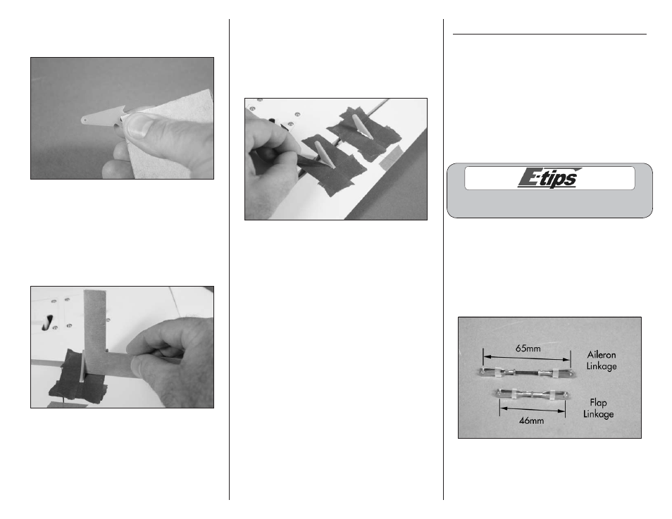
1. Use a hobby knife to cut four 1/4-inch (6mm)
pieces of silicone tubing. Assemble the aileron
linkage using the silicone tubing, two 2mm nuts,
two metal clevises, and a 2mm x 25mm threaded
rod. Assemble the flap linkage using the silicone
tubing, one 2mm nut, two metal clevises, and a
2mm x 25mm threaded rod. Use the length in the
photo as a starting point for the length of the rod.