Watts Autotrol Magnum (CV+ Series) User Manual
Page 9
5
Hydraulic Output Signal
An optional hydraulic output signal is available on the
valve. An optional cam lobe on pilot valve #6 is used on
the camshaft assembly to initiate the hydraulic output
signal during regeneration or backwash (Figure 2.9).
The hydraulic line pressure signal will be available
through the 1/4-inch connection on the back of the
valve marked “AUX”. (Remove the tube cap installed
for shipping.)
Optional cam lobes available are:
P/N 1000554 Provides a hydraulic signal from the
beginning of BACKWASH through the
start of REFILL.
P/N 1000553 Provides a hydraulic signal from the
beginning of BACKWASH through the
end of REFILL.
P/N 1001622 Used on Twin Alternating Systems
Only. Provides a hydraulic signal from
the beginning of BACKWASH through
and during STANDBY.
P/N 1041064 Breakaway cam. Can be programmed
to send a hydraulic signal at any time
during the REGENERATION or
BACKWASH cycle. Note: The camshaft
must be turning for the signal to change
states, i.e. switch from OFF to ON, or
from ON to OFF.
Figure 2.9
Figure 2.10
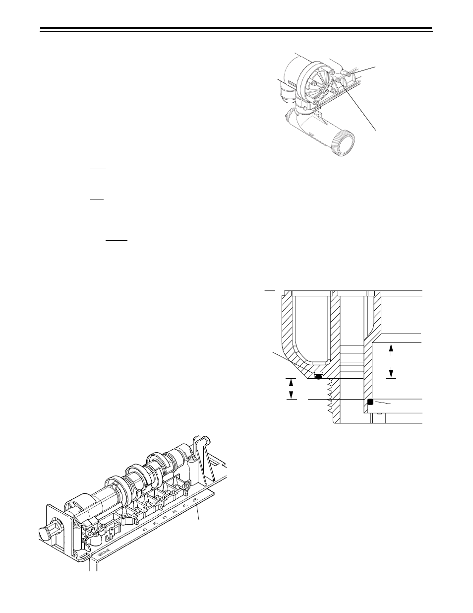
Magnum Tank Adapter
The tank adapter on the control valve is designed to be
compatible with a 4 inch-8UN (8 threads per inch) tank
opening. In addition, the adapter is designed to accept
a full 1-1/2-inch (3.81-cm) riser pipe with outside
diameter of 1.90 to 1.91 inches (48.26 to 48.51 mm)
(Figure 2.11). The riser pipe is sealed by an O-ring on
the inside of the tank adapter, Figure 2.11. It is
recommended that the riser pipe extend beyond the
top of the tank by 1/4 inch ± 3/8 inch (6 mm ± 9 mm).
Figure 2.11
Optional Switch Assembly
On single, twin parallel, and triple parallel tank
configurations, a single optional feedback switch kit is
available to provide an electrical signal during the
entire regeneration or backwash cycle (Figure 2.12).
The switch may be wired in the “Normally Open” or
“Normally Closed” position and is rated for 0.1 amp at
125 volts AC. An optional 5.0 amp switch at 1/10 HP
125/250 volts AC is available upon request.
Optional Cam
Lobe Position #6
“Hydraulic Output
For hydraulic output signal
install one of following cam
lobes:
1000553
1000554
1001622
1041064
Signal”
Auxiliary
Hydraulic
Output Port
Pilot Drain Port
“AUX”
.375" (9.52 mm)
0.8125"
(20.64 mm)
O-ring
Top of Tank
O-ring
Riser O-ring
Tank O-ring