0 general installation information – Watts Autotrol Magnum (CV+ Series) User Manual
Page 14
10
3.0 General Installation Information
Please review the following items thoroughly to ensure
an efficient and safe installation of the water treatment
system. Page 12 shows typical installation line
drawings for the Magnum valves.
Operating Conditions -
A minimum dynamic
operating water pressure of 25 psig (172 kPa) is
required for the Magnum control valve to
operate properly.
Water pressure is not to exceed
125 psig (862 kPa). In Canada, water pressure is not to
exceed 100 psig (688 kPa). Water temperature is not to
exceed 100
o
F (36
o
C). Do not subject the valve to
freezing conditions.
Space Requirements - Allow adequate space for the
water treatment system and associated piping. The
General Specifications section (pages 7-9) provides
the overall dimensions of the control valve as well as
the dimensional reference information for each of the
connection ports. A minimum of 4 1/2 inches (11.5 cm)
front and rear clearance is required for cartridge
assembly and removal.
Plumbing - Always follow good plumbing practices
and conform to local codes. Check existing pipes for
lime and/or iron buildup. Replace piping if heavy
buildup exists and initiate the proper treatment to
prevent additional occurrences. Locate the equipment
close to a drain that is capable of handling the
maximum drain flow rate during backwash.
Flexible Connectors - Some tanks expand and
contract over the acceptable range of operating water
pressures of the Magnum control valve. The use of
flexible connectors is recommended on polywound or
fiberglass tank installations of 24-inch (60.96-cm)
diameter and larger. Follow the tank manufacturer’s
instructions for more information.
Inlet and Outlet Piping - Inlet and outlet plumbing
should be adequately supported to avoid excessive
loads on the valve. Install a manual bypass system to
provide for occasions when the water conditioner must
be bypassed for servicing.
Drain LIne Piping - To prevent mineral loss during
backwash, and to ensure proper operation of the
Magnum Cv Series control valve, A DRAIN LINE
FLOW CONTROL must be plumbed into the drain line
prior to placing the valve in the service mode. Flow
controls from 5 to 40 gpm (18.92 to 151.4 Lpm) are
available from GE Osmonics and can be easily installed
in the drain line (Figure 3.1). Flow controls greater than
40 gpm (151.4 Lpm) must be plumbed externally.
Selection of the proper drain line flow control will
depend on the tank size and media used for the
installation. See Table 10.3.
The following general drain line piping guidelines
should be observed:
•
1 inch (2.54 cm) or larger piping
•
Should not exceed 20 feet (6.1 m)
•
Should not be elevated higher than the control
valve
•
No shut-off valves should be installed in drain line
•
Minimal number of elbows and fittings should be
installed in drain line
•
Piping must be self-supporting
•
Install air gap to provide a siphon break
•
Flow control should be installed as close to the
Magnum Cv Series control valve as possible if an
external flow control is used.
Figure 3.1
Brining System - The Magnum control valve utilizes
timed water refill to add water to the salt tank. A refill
tube with check ball is required in the brine tank that will
not restrict the refill or brine draw flow rate capabilities
of the valve. Although not required, a separate brine
valve (safety float) system is recommended for use with
Magnum installations. Select a “High-Flow” brine valve
that will not restrict the refill or brine draw flow rate
capabilities of the valve. The “Performance Data and
Charts” section (Section 10.0) of this manual contains
flow rate information for various size injectors and refill
controllers.
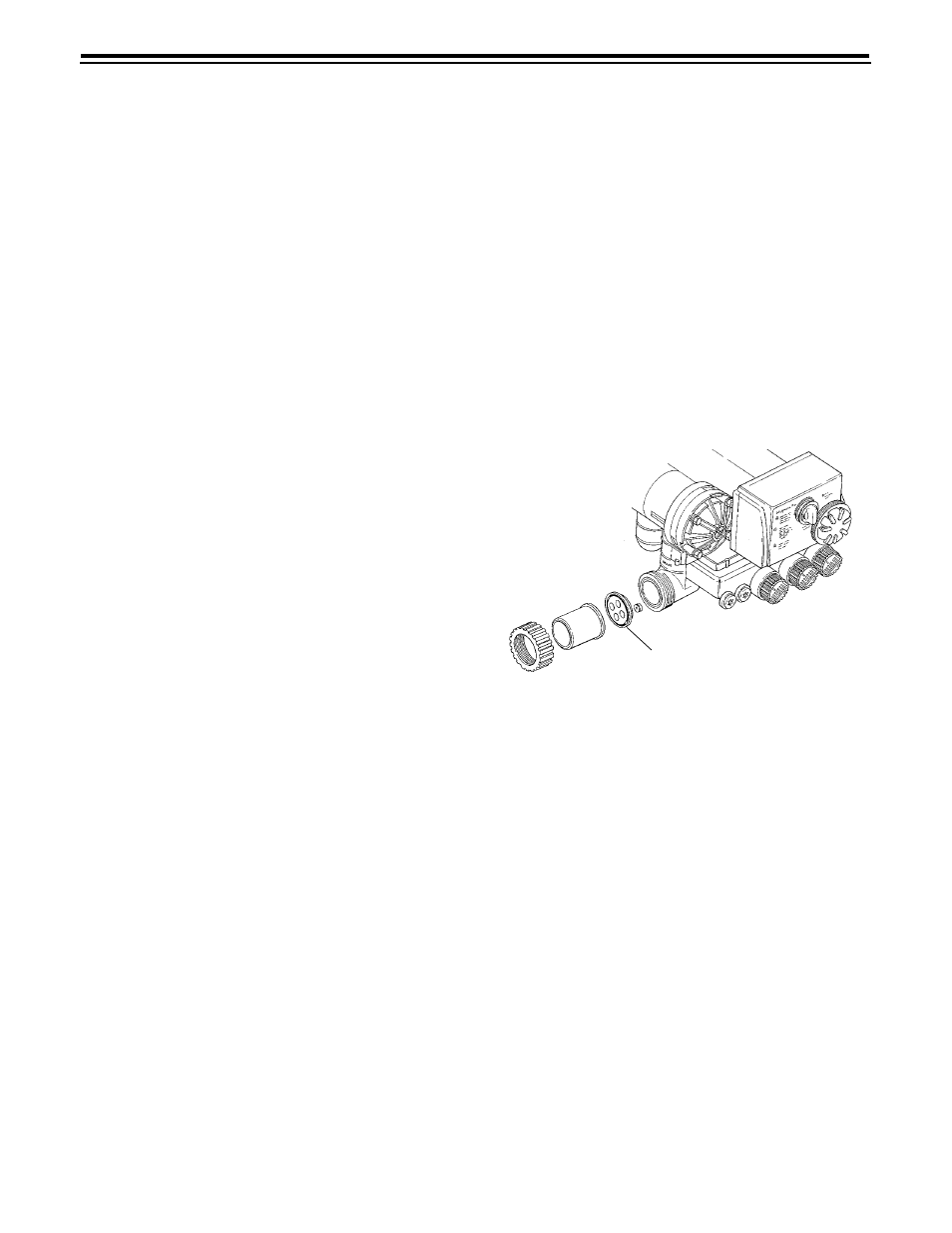
Pilot Drain - During regeneration, a small amount of
water (200 ml or 1 cup) is discharged from the 1/4-inch
(6.3-mm) tube fitting on the back of the valve marked
DRAIN (Figure 3.2). To prevent this water from being
discharged to the floor, plumb this connection to a non-
pressurized drain or to the brine tank. Do not plug or
apply back pressure to the pilot drain at any time.
Crimping the pilot drain line or installing the line to go
up, which causes backpressure, will prevent the
diaphragm cartridges from shifting properly through
the cycles of regeneration or backwash.
Drain Line Flow Control Disk