0 flow diagrams – Watts Autotrol Magnum (CV+ Series) User Manual
Page 17
13
4.0 Flow Diagrams
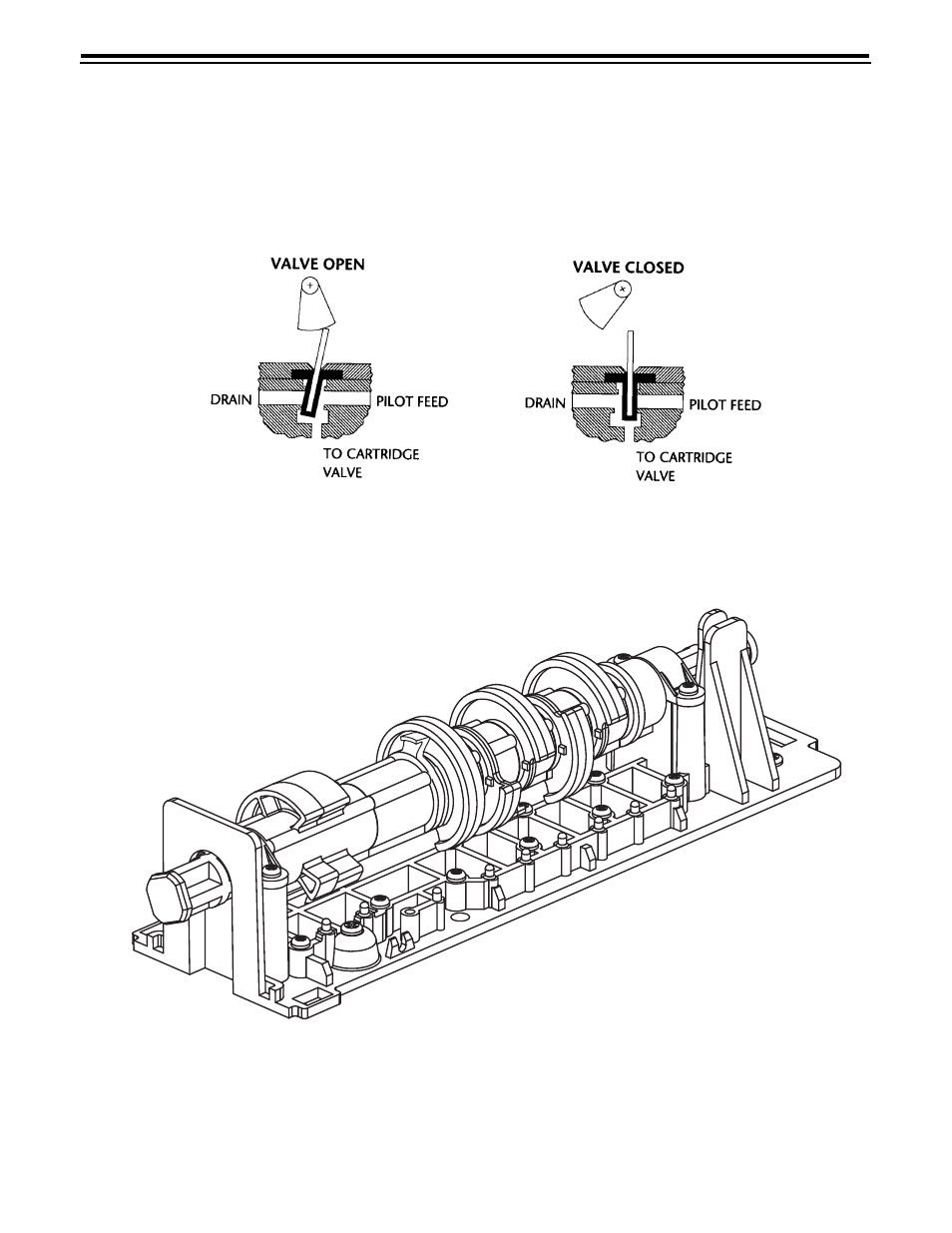
The Magnum control valve utilizes a series of pilot
valves to properly position the diaphragm valve
cartridges (Figure 4.1). The pilot valves are activated by
the camshaft (Figure 4.2). The flow diagrams that follow
represent the Service Cycle for a 5-cycle softener,
3-cycle filter, and 5-cycle twin alternating softener
configuration. Both the Hardwater Bypass and No
Hardwater Bypass service flow diagrams are
presented.
Figure 4.1 Pilot Valve Principle of Operation
Figure 4.2 Cam Assembly
See also other documents in the category Watts Accessories for water:
- PWMBVIH (4 pages)
- PWHSMULTI (2 pages)
- M100 / M1100 (2 pages)
- M113-41 (2 pages)
- M113-41 (1 page)
- 210-5 (2 pages)
- LF210-5 (2 pages)
- 88-CSI (2 pages)
- 1023B (2 pages)
- FD-200-RS (1 page)
- PWRO440 (8 pages)
- PWRO440 (2 pages)
- FD-200-VS (1 page)
- M6115-74 (7 pages)
- R44-16-1111000 (2 pages)
- R44-16-1111000 (40 pages)
- EMVII-6400-SS (2 pages)
- EMVII-6400-SS (4 pages)
- DBF-03 (2 pages)
- F110-10 (2 pages)
- F110-14 (6 pages)
- F113-6RFP (16 pages)
- 007DCDA (54 pages)
- LF709 (4 pages)
- 709DCDA (4 pages)
- LFWP19B (2 pages)
- WP12P-0812PB (2 pages)
- A-158A (1 page)
- A-158A (2 pages)
- RD-900 (1 page)
- M127-32 (1 page)
- M127-32 (2 pages)
- LF919 (3 pages)
- 919 (8 pages)
- M115-11 (2 pages)
- M115-11 (1 page)
- FS-720 (1 page)
- F116-5 (2 pages)
- F116-5 (1 page)
- 656 (1 page)
- LFN170 (2 pages)
- LFN170 (1 page)
- LFN170 (12 pages)
- LFN170 (2 pages)
- 288 1003 (1 page)