4 inputs and outputs – Banner SureCross DX80 Wireless Networks User Manual
Page 82
Message Code
[15:8]
Data Field [7:0]
Description
FE
--
Modbus register 8 device messages are disabled. The Modbus register 8 clears or disables
messages using the Gateway’s Modbus register 15. (Decimal values 65024 through 65279.)
10.4 Inputs and Outputs
Some inputs or outputs are not working.
Option 1. From the Node, access the menu system and use manual scrolling mode within *RUN to freeze the I/O status on
the LCD display for the device in question. Verify that when the input device changes state or changes value, the LCD
mirrors the behavior. If the Node is in a hazardous location, access the Node's I/O from the Gateway by changing the
Gateway's right rotary dial to the Node number in question. For example, to view the I/O status of Node 3, move the
Gateway's right rotary dial to 3. The Gateway's LCD now scrolls through Node 3's I/O. To freeze the display on a particular
I/O point, double-click button 2. The autoscrolling on the Gateway stops at the *RUN screen. Single-click button 1 to
advance through the Node's I/O points.
Option 2. Verify the LCD on the output side mirrors the linked input’s behavior. If the input device state LCD on the
origination DX80 and the LCD on the destination DX80 behave the same, there may be a wiring issue or an interfacing
problem. Consult the factory.
Option 3. Nodes will not sample inputs unless the Nodes are in sync with a Gateway. Verify your Node is in sync with its
Gateway.
10.5 Radio Link Time-Out and Recovery (Non-Host Connected Systems)
The SureCross
®
wireless devices employ a deterministic link time-out method to address RF link interruption or failure. As
soon as a specific Node/Gateway RF link fails, all pertinent wired outputs are de-energized until the link is recovered (see
component data sheet for more information.) Through this process, users of Banner wireless networks can be assured that
disruptions in the communications link result in predictable system behavior.
The link time-out feature uses a fully-acknowledged polling method to determine the RF link status of each Node on the
network.
If after a specified number of sequential polling cycles the Node does not acknowledge a message, the Gateway considers
the link with that Node timed out. LCD displays on both the Node and Gateway show *ERROR. Following a time-out, the
Node de-energizes outputs and the Gateway sets all outputs linked to the Node in question to a de-energized state. Inputs
from the Node mapped to outputs on the Gateway are suspended during a link time-out.
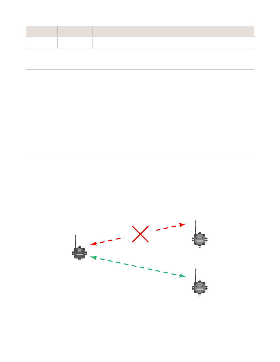
Gateway
Node 1
Node 2
OUT 1 = 0
OUT 2 = 0
OUT 1 = Normal
OUT 2 = Normal
OUT 1 = 0
OUT 2 = 0
OUT 3 = Normal
OUT 4 = Normal
Figure 3. Radio link between the Gateway and Node 1 has timed out.
After a link has failed, the Gateway must receive a specified number of good RF communications packets from the Node in
question before the link is reinstated. Outputs are restored to current values when the link is recovered.
SureCross Wireless I/O Networks
82