Banner SureCross DX80 Wireless Networks User Manual
Page 49
5.9.1 Interpreting Register Values in the Banner Wireless System
The units conversion table defines the type and range of values for each type of I/O.
The wireless devices have many different units of measure for inputs including: milliamp (mA), voltage (V), temperature
(°C or °F), humidity (RH), or a raw 16-bit or 32-bit value. Outputs can be either current (4 to 20 mA, 0 to 20 mA) or
voltage (0 to 10 V dc). All values stored in Modbus registers are unsigned numbers, except for temperature readings. The
temperature readings are stored as signed numbers (two's complement).
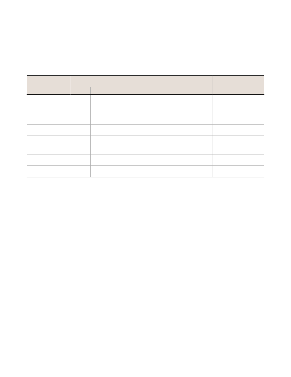
The following table defines the range of values and descriptions for input units.
Input Type
I/O Range
Holding Register
Representation
Data Conversion
Description
Min.
Max.
Min.
Max.
Discrete
0
1
0
1
-
-
0 to 20 mA
0.0 mA
20.0 mA
0
65535
(20 mA ч 65535) Ч Reg
Value = mA
Linear mapping of unsigned
register value to current
4 to 20 mA
4.0 mA
20.0 mA
0
65535
((16 mA ч 65535) Ч Reg
Value) + 4 = mA
Linear mapping of unsigned
register value to current
0 to 10 V dc
0.0 V dc
10.0 V dc
0
65535
(10 V ч 65535) Ч Reg Value
= V
Linear mapping of unsigned
register value to voltage
Temp C/F (high
resolution)
–1638.3
+1638.4
0
65535
(Converted Reg Value) ÷ 20
= Temp
Signed Values
Counter
0
65535
0
65535
-
-
16-bit T30UF
0 mm
65535 mm
0
65535
None; stored as millimeter
value
Unsigned
Humidity
0% RH
100% RH
0
10000
(Reg Value) ÷ 100 = Relative
Humidity (RH)
Unsigned
Temperature Measurements:
•
In high resolution mode, the temperature = (Modbus register value) ÷ 20. For high resolution temperature input, 0
in the register is interpreted as 0° and 65535 in the register (0xFFFF) is interpreted as −1 ÷ 20 = −0.05°.
•
In low resolution mode, the temperature is (Modbus register value) ÷ 2. For low resolution temperature input, 0 in
the register is interpreted as 0° and 65535 in the register (0xFFFF) is interpreted as −1 ÷ 2 = −0.5°. The I/O
range values are –16383 through 16384.
When using a 4 to 20 mA sensor with a 0 to 20 mA input, the sensor uses the 4 to 20 mA section of the total range. Using
a 4 to 20 mA with a 0 to 20 mA input allows you to determine when you have an error condition with the sensor. A normal
input reading between 4 and 20 mA indicates a functioning sensor whereas a value below 4 mA indicates an error
condition, such as a broken wire or loose connection. Some SureCross devices allow you to configure the analog inputs and
outputs to use either 0 to 20 mA or 4 to 20 mA.
5.9.1 Signed Numbers
Temperature values are stored in Modbus registers as two's complement signed numbers. Using two's complement allows
negative numbers to be stored in Modbus registers. Although not technically a sign bit, the most significant bit (MSB)
indicates a negative number when the value is set to one (1). When the most significant bit is zero (0), the value is
greater than or equal to zero.
Modbus register values of 32768 through 65535 (decimal) represent negative temperatures. These numbers in binary form
are: 1000 0000 0000 0000 through 1111 1111 1111 1111.
To convert to a negative temperature value from a Modbus register value, first convert the value from the two's
complement number. To convert from a two's complement number in binary form, invert all the bits (0 changes to 1, 1
changes to a 0), then add 1. Convert this binary value to a decimal value and divide by either 20 (high resolution mode) or
2 (low resolution mode) to calculate the negative temperature.
SureCross Wireless I/O Networks
49