3 site survey troubleshooting, 4 conduct a site survey using modbus commands – Banner SureCross DX80 Wireless Networks User Manual
Page 19
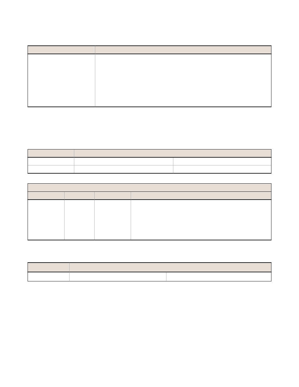
3.7.3 Site Survey Troubleshooting
Some tips and tricks about improving radio signal reception may improve the site survey results.
Problem
Solution
Marginal Site Survey (RSSI)
Results
If the distance between devices is greater than about 5,000 meters (3 miles) line-of-
sight *OR* objects, such as trees or man-made obstructions, interfere with the path,
and the MISSED packet count exceeds 40 per 100 packets, consider the following
steps:
•
Raise the DX80 units to a higher elevation, either by physically moving the
devices or installing the antenna(s) remotely at a higher position.
•
Use high-gain antenna(s) such as Yagi and/or Omni (see Accessories).
•
Decrease the distance between devices.
•
Use data radios to extend the position of the Gateway relative to the host
system.
3.7.4 Conduct a Site Survey Using Modbus Commands
Use Modbus commands sent from the host system to start a Site Survey.
To start a Site Survey using a Modbus write holding register command, send a control code of 32 (0x20) and the Node
number 1 through 15 (0x01 to 0x0F) to the Gateway Modbus holding register for I/O 15.
Modbus Register
[15:8]
[7:0]
I/O 15
Control Code
Data Field
I/O 15 Control Messages
Control Code
Data Field
Restrictions
Description
32
Node # 1-15 Gateway only
Enable Site Survey between Gateway and Node defined by the data
field. All error messages from the Gateway are ignored when running
Site Survey.
Only one Node can participate in Site Survey at a time. To disable
the Site Survey, use control code 0x20 with Node 0. A Node must be
enabled to run the Site Survey, then disabled before selecting the
next Node.
3.7.4 Example Command
Modbus Register
I/O 15
32
02
When Site Survey runs, the accumulated results are stored in the Gateway’s I/O 7 and I/O 8 holding registers. The LEDs
on the both the Gateway and the Node’s front panel display the signal strength for the wireless RF link. The quality of the
communications link is indicated by:
LED 1 is green = excellent signal strength
LED 2 is yellow/amber = good signal strength
LED 1 is red = poor signal strength
The signal strength is the transmitted signal strength relative to the ambient RF signal present in a specific location, or
noise floor.
SureCross Wireless I/O Networks
19