5 wiring diagrams, 1 5-pin euro-style wiring for gateways and dx85s, 2 5-pin euro-style wiring for nodes – Banner SureCross DX80 Wireless Networks User Manual
Page 10
1
2
3
4
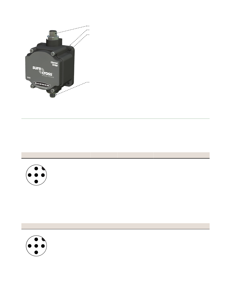
1. Industrial ethernet port, female.
2. Housing. The rugged, industrial DX80 housing meets IEC IP67
standards.
3. Mounting hold, #10/M5 clearance. Mounting Holes accept metric
M5 or UNC/UNF #10 hardware -- DIN rail mount adapter bracket
available.
4. 5-Pin M12 Euro-style quick-disconnect serial port
2.5 Wiring Diagrams
Use the following drawings to correctly wire power and I/O to the SureCross Wireless radio devices. For more information
about wiring sensors to the SureCross devices, refer to Sensor Connections.
2.5.1 5-pin Euro-Style Wiring for Gateways and DX85s
Wiring the 5-pin Euro-style connector depends on the model and power requirements of the device. Connecting dc power
to the communication pins will cause permanent damage.
Wire No.
Wire Color
Description
1
2
3
4
5
1
Brown
10–30V dc
2
White
RS485 / D1 / B / +
3
Blue
dc common (GND)
4
Black
RS485 / D0 / A / –
5
Gray
Comms Gnd
2.5.2 5-pin Euro-Style Wiring for Nodes
Wiring the 5-pin Euro-style connector depends on the model and power requirements of the device. Not all models can be
powered by 10 to 30 V dc and not all models can be powered by 3.6 to 5.5 V dc. Refer to the Specifications to verify the
power requirements of your device. For FlexPower devices, do not apply more than 5.5 V to the gray wire.
Wire No.
Wire Color 10 to 30 V dc Powered
Battery Powered
1
2
3
4
5
1
Brown
10 to 30 V dc
2
White
3
Blue
dc common (GND)
dc common (GND)
4
Black
5
Gray
3.6 to 5.5 V dc
SureCross Wireless I/O Networks
10