2 theory of operation – Metrohm 750 Autosampler User Manual
Page 5
1 Introduction
750 Autosampler
2
1.2
Theory of operation
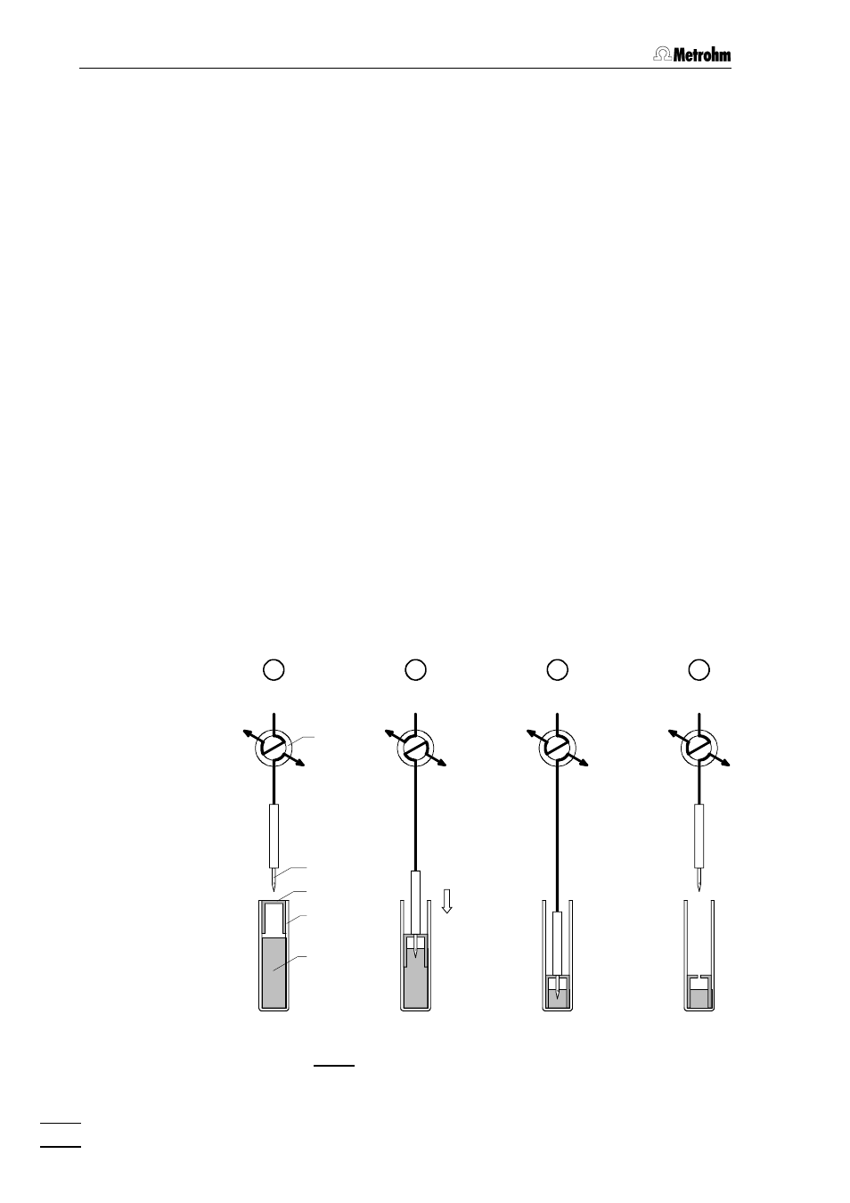
Displacement principle
The 750 Autosampler operates using the positive displacement princi-
ple of sample transfer. This sample transfer process into the sample
loop of the 733 IC Separation Center is illustrated in Fig. 2. When an in-
jection is initiated, the hollow transfer needle 55 descends into the vial.
The needle tip punctures the polyethylene cap of the sample vial. The
opening into the needle is located on the side to minimize plugging by
cap material as the cap is punctured. The needle continues downward
until the pushrod contacts the area around the puncture in the cap
which forces the cap down into the vial. The piston action of the cap
pressurizes the sample and forces it up through the needle and the
transfer tubing 88 that is connected to the needle. From the transfer
tubing, the sample flows through the injection valve and sample loop
with the excess passing on through the waste tube to a waste con-
tainer.
Rinsing by air bubbles
The air bubble (minimum 150
µ
L), which is always present at the top of
a properly filled and capped vial, precedes the sample stream through
the plumbing. The bubble disrupts the laminar flow of the fluid in the
tubing while pushing out the previous sample and solvent. This effect,
in addition to the large excess volume of sample, helps to minimize
sample carryover.
RUN
FILL/LOAD
INJECT
RUN
A
B
C
D
Fig. 2: Positive displacement sample injection
Column
Waste
Eluent
Sample
Needle
Cap
Sample vial
Valve