Metrohm 754 Dialysis Unit User Manual
Page 21
2 Installation
754 Dialysis Unit
18
754
733
A
B
19
45
46
47
48
49
21
23
20
17
27 26
50
50
29
31
30
28
33
34
24
25
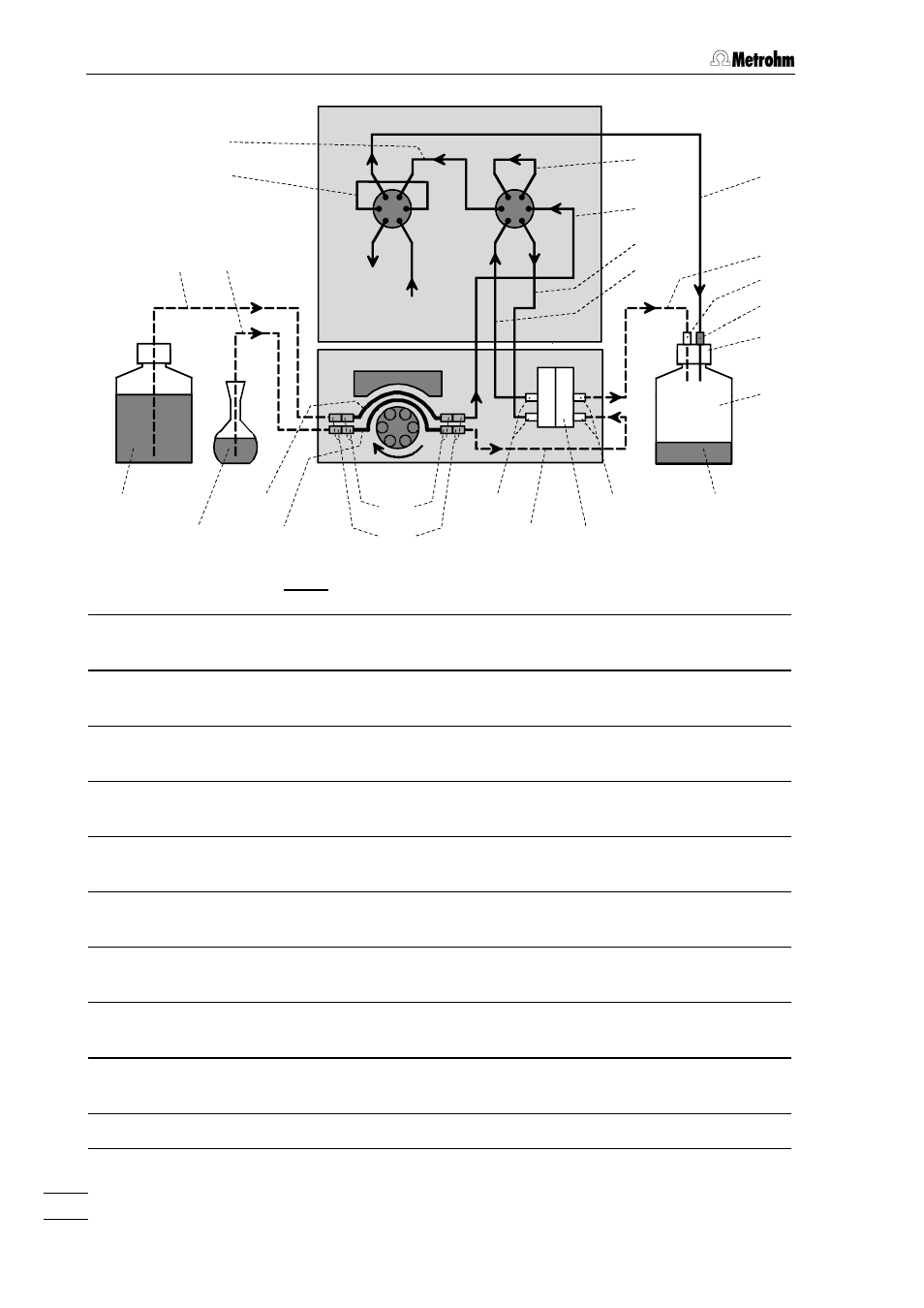
Fig. 8: Diagram of tubing connections
17
17 PEEK sample loop
(6.1825.210; 20
µµL)
30
30 Pump tubing (6.1826.040)
for conveying the sample
19
19 PEEK capillary (6.1831.060; 1 m)
Connection Valve A – Waste
31
31 Pump tubing (6.1826.030)
for conveying the acceptor solution
20
20 PEEK capillary (6.1831.040; 15 cm)
Connection Valve A – Valve B
33
33 PTFE capillary (6.1803.050; 20 cm)
Connection Pump tubing – Dialysis cell
21
21 PEEK capillary (6.1831.040; 15 cm)
Connection at Valve B
34
34 Dialysis cell (6.2729.100)
23
23 PEEK capillary (6.1831.050; 40 cm)
Connection Pump tubing – Valve B
45
45 PTFE capillary (6.1803.040; 1 m)
Connection Dialysis cell – Waste
24
24 PEEK capillary (6.1831.050; 40 cm)
Connection Valve B – Dialysis cell
46
46 PVDF compression fitting
(6.2744.000)
25
25 PEEK capillary (6.1831.050; 40 cm)
Connection Valve B – Dialysis cell
47
47 PEEK compression fitting
(6.2744.010)
26
26 PTFE capillary (6.1803.030)
for feeding the sample in
48
48 Bottle attachment (6.1602.150)
27
27 PTFE capillary (6.1803.030)
for feeding in the acceptor solution in
49
49 Waste bottle (6.1608.070)
28
28 PEEK compr. fitting (6.2744.010)
50
50 PVDF compr. fitting (6.2744.000)
29
29 Coupling (6.2744.030)
Column
Eluent
Sample
Acceptor
Waste