3 attaching the accessories – Metrohm 754 Dialysis Unit User Manual
Page 13
2 Installation
754 Dialysis Unit
10
2.3
Attaching the accessories
2.3.1
Electrical connection to the 732 IC Detector
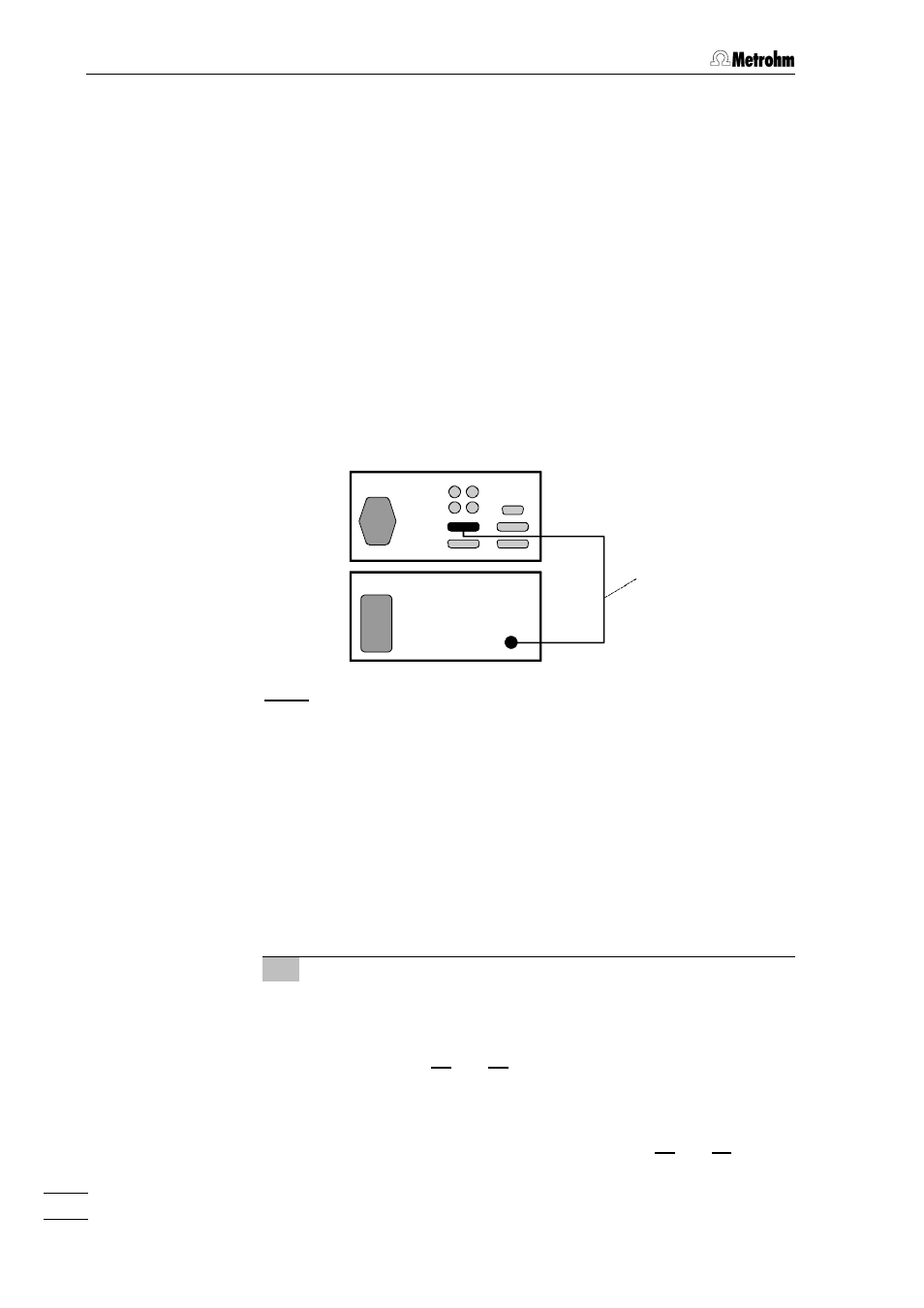
In order to allow remote operation of the pump via the 732 IC Detector,
connection 15
15 of the 754 Dialysis Unit must be connected to the
"Remote" connection of the 732 IC Detector by means of the
6.2143.200 cable as per Fig. 4. The switch 22
of the 754 Dialysis Unit must additionally be set to "ON" to permit re-
mote operation.
If you wish to connect a second, additional unit (e.g. 752, 753, 754) to
the remote interface of the 732 IC Detector, connect the Dialysis Unit
754 using the optionally available 6.2143.220 cable instead of the
6.2143.200 cable.
6.2143.200
754
732
Fig. 4: Connection of 754 Dialysis Unit to 732 IC Detector
2.3.2
Attaching the accessories to the 733.0020 IC Separation
Center
The 2.733.0020 IC Separation Center comes ready to operate with two
IC columns. To operate it with the 754 Dialysis Unit, reassemble it as
follows (see Fig. 5 and Fig. 8):
1 Dismantle accessories
•
Unscrew the two sample loops mounted on valve A 18
18 and
valve B 22
22.
•
Loosen the rotary nipples screwed onto the interior side of
feedthrough 22
22 and 28
28, pull the two PTFE suction tubings
right out of the connections and unscrew from connection "1"
of valve A 18
18 and valve B 22
22.
•
Remove the PEEK capillaries running from connection "2" of
valve A 18
18 and valve B 22
22 to feedthroughs 21
21 and 27
27.