Configuring the rmc – ClearCube R-Series Data Center Products User Manual
Page 75
R-Series Data Center Products User’s Guide
Chassis and Blade Installation • 51
Configuring the RMC
The following steps outline the process required to set up and configure your choice of
chassis control computer/server. These steps also explain the setup of the
communication link to the chassis. This description assumes that you are choosing to
control your chassis with an RMC, rather than with the recommended RMM.
•
Select your chassis control computer/server: For browser-based control you
can use a PC blade or a third-party box PC, server, or a notebook computer that
has an Ethernet connection. This computer/server does not need to be dedicated
solely to this function—it can also be used for other tasks depending on the
application.
•
Connect your control computer to the network: Your control computer must be
on the same LAN that connects to the Ethernet control port of the Primary chassis
with the RMC installed.
•
Connect the Primary chassis and RMC to the network: An RMC can be
installed in either a BSBP or a DCBP. If an RMC is installed in a Control Chain
that contains R4300 chassis with RMMs, the Primary chassis is always the one
that has the RMC installed. The Primary chassis is indicated by a LED on the back
of the chassis next to the control in/out ports that are colored green. When the
ENET indicator is lit, this means that an RMC card is installed and this is a
Primary chassis. If the RS-485 indicator is lit, it means that this is a Slave chassis.
If you have more than one rack of chassis, you will have multiple Primary chassis,
typically one per rack.
•
Daisy-chain multiple chassis: If your installation has multiple chassis, then
daisy-chain the RS-485 control connections with C/Port cables. A green cable is
provided with the chassis. Connect the RS-485 Control Output from the first
BackPack to the RS-485 Control Input on the next BackPack/chassis. Continue
daisy-chaining until all chassis are connected. You can connect all 14 chassis in a
rack together in this way. Additional chassis require an RMC for each rack of
chassis.
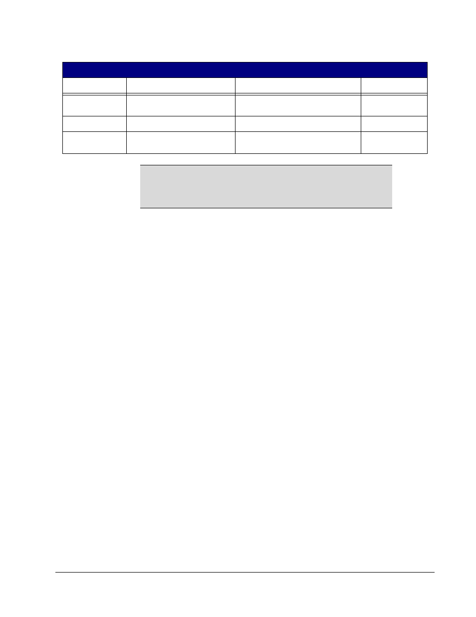
Timestamp
Timestamp
Seconds since Jan. 1, 1970
Set from real-time
clock
RMMPoll
RMM Poll
Time period for RMM “heartbeat”
5 minutes
SMIP2
Sentral Secondary Console IP
Address
xxx.xxx.xxx.xxx 192.168.1.252
NOTE
For failover between Primary and Secondary RMMs to occur
successfully, the RMMs must have the same password, and
Alerting and Logging must be activated. See the Sentral
Administrator’s Guide for more information.
Table 10 R4300 RMM Default Configuration Settings (Continued)
Field Name
Function
Setting Options
Default Setting