ClearCube R-Series Data Center Products User Manual
Page 52
28 • Chassis and Blade Installation
R-Series Data Center Products User’s Guide
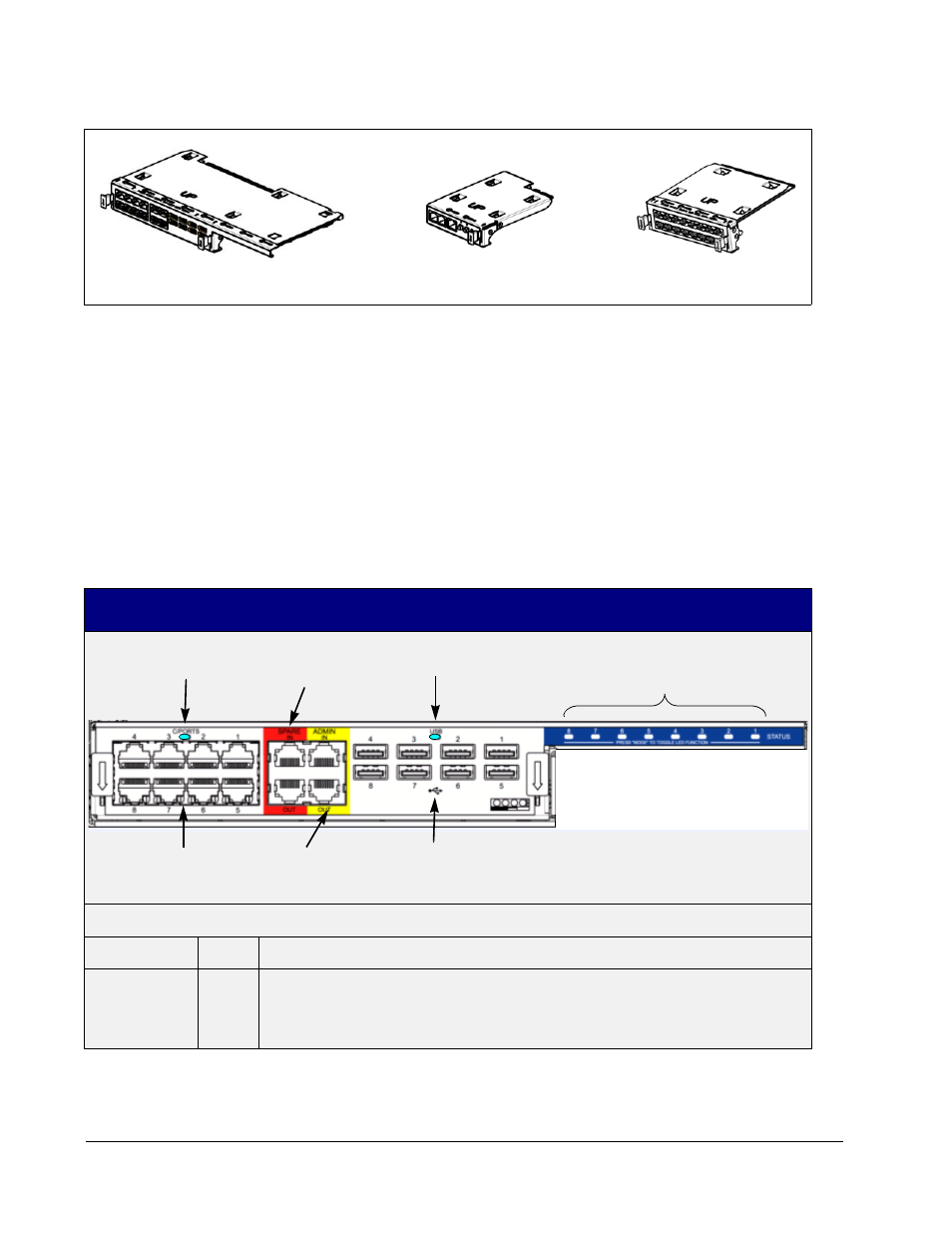
Figure 21 R4300 Modules
The Connect Module (shown on the left in Figure 20) provides connectors for C/Ports,
USB ports, and sparing. On the right, the Network Module (either Model R4362 [EP6] or
Model R4363 [EP2]) provides Ethernet connections. In the center, the Remote
Management Module provides network and daisy-chain control connections, chassis
health indicators, and fan speed control. The Status LEDs in the blue area above the
Management Bay are shared between the sets of connectors to provide information about
each kind of connection to each blade in a manageable fashion.
Table 4 on page 28 provides details of the features of the modules, and describes their
interactions. Note that some features are color-coded to show that their functions are
inter-related. For example, features coded blue are for monitoring the status of the
various connection ports on the R4300.
Table 4 R4300 Connect Module Features
Connectors
Label
Color
Description
ADMIN IN
Yellow
RJ45 connection that links the Admin C/Port into the Admin daisy chain, or passes the
Admin connection to another chassis by connecting to that chassis’ ADMIN OUT port.
As many as 14 chassis per Control Chain can be connected on one Admin daisy chain.
A Control Chain can have more than one Admin daisy chain.
Connect Module
Management Module
Network Module
USB Selected LED
Status LEDs
Selected LED
Digital Link
C/Port Connections
USB Connections
Spare
Daisy Chain
Connections
Admin
Daisy Chain
Connections