ClearCube R-Series Data Center Products User Manual
Page 117
R-Series Data Center Products User’s Guide
Hardware Upgrade and Replacement Procedures • 93
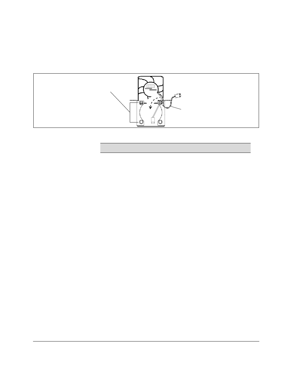
9. Insert the replacement fan in the fan bracket.
a.
Rest—but do not insert—the new fan in the top of the fan bracket, ensuring
that:
–
The fan and the bracket are facing forward (a label is on the front of the
fan and the front of the bracket has four mounting holes).
–
The power cord is behind the mounting hole.
b. Push the fan down to fully seat it in the bracket (push out of the flanges on the
top of the bracket to ease insertion).
c.
Ensure that the power cable exits the fan on the correct side. Figure 48 on
page 90 shows the correct power cable positioning for each fan.
10. Place the fan and bracket in the blade. Ensure that CPU fan 0 is in the left slot, and
CPU fan 1 is in the right slot, as shown in Figure 49 on page 91. Replace both
screws in the holes on the top of each bracket and tighten.
11. Connect each fan’s power cable to the appropriate fan header. Carefully use your
fingers or needle-nose pliers to push the cable socket onto the header. Ensure that
you do not loosen memory modules, VRMs, or other components.
12. Reconnect all SATA data and power cables to the hard disks in the hard disk tray.
Ensure that you reconnect all data cables exactly as they were before you
disconnected them. See “R3040S Hard Disk Tray, Drive Layout, and SATA
Headers on Motherboard” on page 85 for more information.
13. Replace the hard disk tray and secure the tray with the four screws that you
previously removed.
14. Ensure that all SATA cables are fully seated on the motherboard headers, and that
all memory modules and VRMs are fully seated. You can now replace the blade in
a chassis, as described in “PC Blade Installation” on page 58, and power on the
blade.
NOTE
Do not insert screws in fan bracket. No screws are required.
Ensure Fan and Bracket
Are Facing Forward
Move Power Cord Behind Flanges
Before Inserting
DO NOT INSERT SCREWS
IN BRACKET