Installation instructions – Brandmotion 1009-9518 User Manual
Page 7
INSTALLATION INSTRUCTIONS
9518 Instructions 6-26-13.Doc
Page 7 of 7
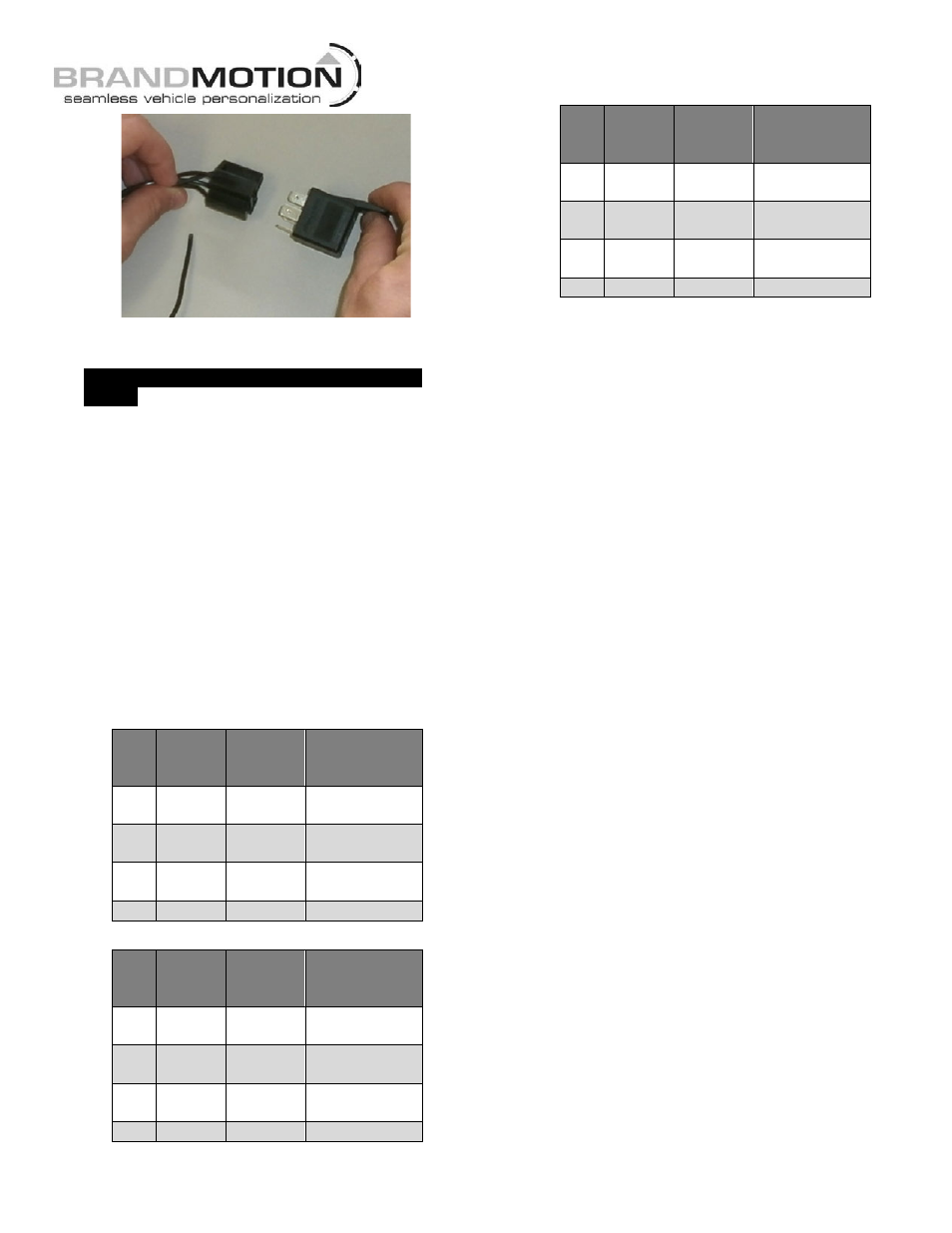
48. Connect supplied Mirror Harness 6-pin connector to
supplied Chassis Harness.
49.
If your vehicle is equipped with a uConnect
mirror,
an aftermarket Microphone (available
separately as Brandmotion kit 5000-PESMVR) must
be installed to maintain voice operation. If your
vehicle is NOT equipped with a uConnect mirror,
proceed to Step 50.
A. Five wires are supplied in the microphone kit:
(1) Yellow - Microphone +
(1) Blue - 12V +
(3) Black - Ground. All three black wires are
identical and are joined together inside the
harness. Additionally, the third black Ground wire
will NOT be used in this application.
B. Make the following connections based upon
whether the vehicle has a 7-pin, 10-pin, or
14-pin Mirror Connector:
14 pin mirror connector
Pin
#
Mic
Wire
Color
Polarity Function
7
Blue
+
Ignition 12
volts
11
Yellow
+
Microphone
Positive
12
Black
–
Microphone
Negative
14
Black
–
Ground
10 pin mirror connector
Pin
#
Mic
Wire
Color
Polarity Function
5
Blue
+
Ignition 12
volts
8
Yellow
+
Microphone
Positive
9
Black
–
Microphone
Negative
4
Black
–
Ground
7 pin mirror connector
Pin
#
Mic
Wire
Color
Polarity Function
1
Blue
+
Ignition 12
volts
4
Yellow
+
Microphone
Positive
3
Black
–
Microphone
Negative
2
Black
–
Ground
C. Microphone Wire Connection techniques:
Brandmotion recommends that you DO NOT
cut any wires. Instead, either use the “strip
and splice” method or use T-tap connectors
to make your connections. When making
your connections particularly with T-taps, be
certain to test fit any trim pieces, which will
need to be reinstalled on the vehicle.
Strip and Splice: This method requires the
following steps and is recommended for best
results.
§
Strip back a small portion of the insulation from
the wire.
§
Using a small wire pick, separate the exposed wire
into two groups.
§
Insert the corresponding wire from the kit through
the center as if you were threading a needle.
§
Twist excess wire around the exposed area tightly
and cover with heat shrink tubing or wrap with
electrical tape.
§
Use a Tie Wrap/ Zip Tie to secure your connection
by placing it over the taped portion of the wire
where the junction was made.
Using T-tap connectors:
Use red T-tap connectors
as all the wires that you will be attaching to are of
small gauge and larger T-taps will create false
contacts which will not allow the system to
function properly.
D. Using adhesive tape supplied in the
microphone kit, mount the microphone in the
desired position.
E. Route the cable attached to the microphone
to the location where you made your
connections and plug in the connector.
F. Prior to vehicle reassembly, test microphone
for function with uConnect according to
uConnect operating instructions contained in
vehicle owner’s manual.
50. Start vehicle and shift into Reverse in order to check
that all connections were made properly. If all of the
connections are correct you will see a video image
displayed on your aftermarket display.
51. Reassemble vehicle.