Installation instructions – Brandmotion 1009-9518 User Manual
Page 6
INSTALLATION INSTRUCTIONS
9518 Instructions 6-26-13.Doc
Page 6 of 7
44. Carefully twist on the supplied Mirror approximately
30 degrees until it clicks into place.
45. Tuck existing mirror wiring under headliner and
route supplied Mirror Harness down driver’s A-pillar.
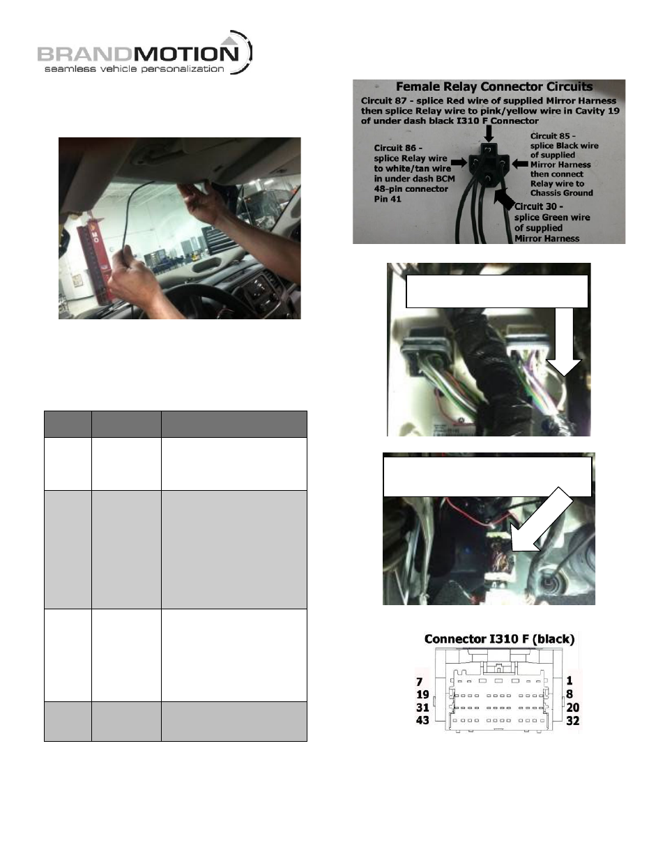
46. Using the supplied female Relay connector (Figure
1), splice the leads of the supplied Mirror Harness
into the wires of each numbered circuit as follows
(Recommended: Solder and cover with Heat Shrink
Tubing.):
Mirror Harness & Relay Connections
Circuit
Function/
Polarity
Connection
86
Reverse
(+)
Splice Relay wire to
white/tan wire in under
dash BCM white 48-pin
connector Pin 41 (Figure 2)
87
Ignition
(12v +)
Splice Red (Ignition) Mirror
Harness lead to Relay wire.
Then splice Relay wire to
pink/yellow wire in Cavity
19 of under dash black
I310 F Connector adjacent
to parking brake cable
grommet
(Figures 3 & 4)
85
Ground
(–)
Splice Black (Ground)
Mirror Harness lead to
Relay. Then splice Relay
wire to Chassis ground –
attach Eyelet to an existing
ground bolt or use a nut to
secure to an existing stud.
30
Reverse
(+)
Splice Green (Reverse) wire
of supplied Mirror Harness
to Relay wire.
Figure 1
Figure 2
Figure 3
Figure 4
47. Plug the supplied male Relay connector into the
female Relay connector and secure to existing
vehicle wiring using a supplied Wire Tie.
Splice Circuit 86 Relay wire to Reverse (+)
signal at white/tan wire in Pin 41.
Splice Circuit 87 Relay wire to Ignition (12v +)
signal at pink/yellow wire in Cavity 19.