Rockwell Automation 1769-L23E-QB1B_L23E-QBFC1B_L23-QBFC1B CompactLogix Packaged Controllers Quick Start and User Manual User Manual
Page 209
Publication IASIMP-QS010B-EN-P - October 2009
209
Embedded I/O Chapter 3
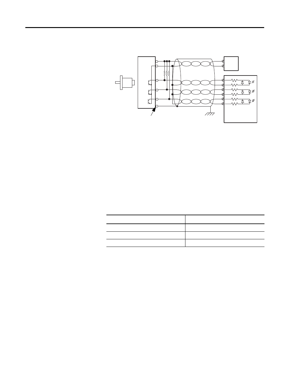
Single-ended Encoder Wiring
(1) Refer to your encoder manual for proper cable type. The type of cable used should be twisted-pair, individually
shielded cable with a maximum length of 300 m (1000 ft).
(2) External resistors are required if they are not internal to the encoder. The pull-up resistor (R) value depends on
the power supply value. The table below shows the maximum resistor values for typical supply voltages. To
calculate the maximum resistor value, use this formula:
where:
R = maximum pull-up resistor value
V DC = power supply voltage
Vmin = 2.6V DC
Imin = 6.8 mA
Resistor Values for Supply Voltages
Power Supply Voltage
Pull-up Resistor Value (R), max
(1)
(1)
Resistance values may change, depending upon your application.
The minimum resistor (R) value depends on the current sinking capability of the encoder. Refer to your encoder’s
documentation.
5V DC
352
Ω
12V DC
1382
Ω
24V DC
3147
Ω
A
B
Z
A1(+)
A1(–)
B1(+)
B1(–)
Z1(+)
Z1(–)
GND
VS
+VDC
COM
R
(2)
Cable
(1)
Power
Supply
Allen-Bradley
845H Series
single-ended
encoder
Shield/Housing
Connect only if housing is electronically
isolated from the motor and ground.
Shield
Inputs
Earth
R
V
d
c
Vmin
–
(
)
Imin
---------------------------------------
=