4 wiring the control terminal block – Rockwell Automation MD60 User Manual Version 3.0 User Manual
Page 36
6-4
MD60 AC Drive User Manual
6.4
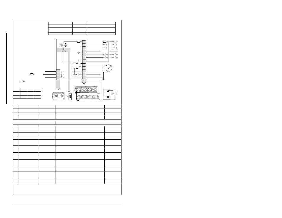
Wiring the Control Terminal Block
No.
Signal
Default
Description
Parameter
R1
Relay N.O.
Fault
Normally open contact for output relay.
A055
R2
Relay Common
–
Common for output relay.
R3
Relay N.C.
Fault
Normally closed contact for output relay.
A055
Sink/Source DIP Switch
Source (SRC)
Inputs can be wired as Sink (SNK) or Source (SRC) via DIP Switch setting.
01
Stop
(1)
Coast
The factory-installed jumper or a normally closed input
must be present for the drive to start.
P036
02
Start/Run FWD
Not Active
Command comes from the integral keypad by default. To
disable reverse operation, see A095 (Reverse Disable).
P036, P037
03
Dir/Run REV
Not Active
P036, P037, A095
04
Digital Common
–
For digital inputs. Electronically isolated with digital
inputs from analog I/O.
05
Digital Input 1
Preset 1
Program with A051 (Digital In1 Select).
A051
06
Digital Input 2
Preset 2
Program with A052 (Digital In2 Select).
A052
11
+24V DC
–
Drive supplied power for digital inputs.
12
+10V DC
–
Drive supplied power for 0-10V external potentiometer.
P038
13
0-10V In
(3)
Not Active
For external 0-10V input supply
(input impedance = 100k ohm) or potentiometer wiper.
P038
14
Analog Common
–
For 0-10V In or 4-20mA In. Analog inputs electrically
isolated from digital I/O.
15
4-20mA In
(3)
Not Active
For external 4-20mA input supply
(input impedance = 250 ohm).
P038
16
RS485 Shield
–
Terminal should be connected to chassis ground when
using the RS485 communications port.
(3)
Only one analog frequency source may be connected at a time. If more than one reference is connected at the same time,
an undetermined frequency reference will result.
(
4) RS485 port is used to connect the drive to a personal computer running VS Utilities via a Serial Converter module, and for
connection to the Remote Nema 4x/12 or Copy Cat Keypads.
Figure 6.1 – Wiring the Control Terminal Block
30V DC 125V AC 230V AC
Resistive
3.0A
3.0A
3.0A
Inductive
0.5A
0.5A
0.5A
(1)
Important: I/O Terminal 01
is always a coast-to-stop input
except when P036 (Start Source)
is set to 3-Wire Control. In three-
wire control, I/O Terminal 01 is
controlled by P037 (Stop
Mode).
All other sources are
controlled by
P037 (Stop Mode).
Important: The drive is
shipped with a jumper
installed between I/O
Terminals 01 and 11.
Remove this jumper when
using I/O Terminal 01 as a
stop or enable input.
(2)
Two-wire control shown.
For three-wire control, use a
momentary input
on
I/O Terminal 02 to command
a start. Use a maintained
input
for I/O Terminal
03 to change direction.
P036 (Start Source)
Stop
I/O Terminal 01 Stop
Keypad
Per P037
Coast
3-Wire
Per P037
Per P037
2-Wire
Per P037
Coast
RS485
Per P037
Coast
01
02
03
04
05
06
11
12
13
14
15
16
Stop
(1)
Start/Run FWD
(2)
Direction/Run REV
Digital Common
Digital Input 1
Digital Input 2
R1
R2
R3
Relay N.O.
Relay Common
Relay N.C.
+24V DC
+10V DC
0-10V In
Analog Common
4-20mA In
RS485 Shield
+24V
+10V
SRC
SNK
Typical
SNK Wiring
Typical
SRC Wiring
1
8
RS485
(DSI)
R1 R2 R3
01
02
03
04
05
06
11
12
13
14
15
16
SNK
SRC
(1)