Interconnect diagrams – Rockwell Automation TLAR Electric Cylinders User Manual
Page 37
TL-Series Electric Cylinders 37
Rockwell Automation Publication TLAR-IN001B-EN-P - February 2014
Interconnect Diagrams
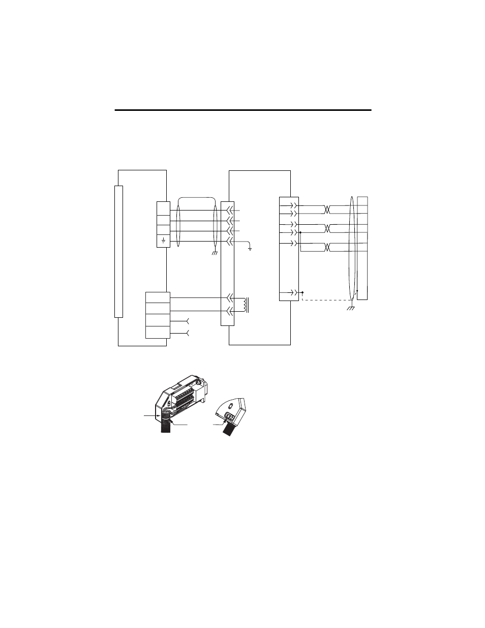
This is an example diagram for wiring your TL-Series electric cylinder and Allen-Bradley servo
drives.
Wiring Example of TL-Series Electric Cylinder to Kinetix 2000 Drive
BR+
BR-
7
8
DATA+
DATA-
+5VDC
ECOM
BAT+
BAT-
ORANGE
WHT/ORANGE
GREEN
WHT/GREEN
GRAY
WHT/GRAY
5
10
14
6
BAT+
BAT-
13
14
22
23
6
0
1
2
3
4
5
6
7
8
9
10
11
12
13
14
15
BLACK
WHITE
24
2
3
1
4
MBRK +
MBRK -
PWR
COM
24V DC
(1.2 A max)
User Supplied
1
2
3
5
U
V
W
1
2
3
4
BROWN
BLACK
BLUE
GREEN/YELLOW
U
V
W
Cable Tie
Exposed shield
secured under
clamp.
Kinetix 2000
IAM (inverter) or
AM Module
TL-Series Electric Cylinder
Motor Power
(MP) Connector
Motor Feedback
(MF) Connector
Motor
Brake
(BC)
Connector
Motor Feedback (MF)
Connector (IAM or AM)
2090-CPWM6DF-16AAxx
Power Cable without Brake or
2090-CPBM6DF-16Axx Power
Cable with Brake
Motor Feedback
Three Phase
Motor Power
GND
2090-CFBM6DF-CBAAxx
(flying lead) or
2090-CFBM6DD-CCAAxx
(premolded connector)
Feedback Cable
Use Low Profile Connector
2090-K2CK-D15M
(feedback only) or
2090-K2CK-COMBO
(Feedback and IO)
Use 2090-K2CK-D15M
- 20P PowerFlex DC Drive - Frame D Bimetal Thermostat (10 pages)
- 1336S_F_T_E_R F Frame Snubber Resistor Repl. (6 pages)
- 22-COMM PowerFlex 4-Class DSI (Drive Serial Interface) Network Communication Adapter (4 pages)
- 8-545 Plug In Solid State Relay (2 pages)
- 20-HIM-B1 PowerFlex 7-Class HIM Bezel (DPI) (4 pages)
- 100 Contactors with DC Coil (1 page)
- 100 Contactors with DC Coil (2 pages)
- 20P PowerFlex DC Drive - Frame D Switching Power Supply Circuit Board (6 pages)
- 140G-MTFx_MTHx_MTIx_MTKx Trip Unit Installation-140G-M (6 pages)
- 45BRD Analog Laser Sensor (4 pages)
- 20D Multi-Device Interface Option Board for PowerFlex 700S Drives (20 pages)
- 56RF RFID 18 mm Cylindrical Transceiver (2 pages)
- 42KC Miniature Rectangular: 5V DC Version (2 pages)
- 20P PowerFlex DC Drive - Frame A Switching Power Supply Circuit Board (16 pages)
- 21P-MISC-A-TP-2 Transition Tube Kit #C19-6/7 For PowerFlex 755 w/OEM Liquid Cooling Fr 6/7 Drive (2 pages)
- 42BT Background Suppression Sensor (3 pages)
- 42CB High Speed 18mm Cylindrical (4 pages)
- 140EX-JE2_JE3 Molded Case Circuit Breaker (4 pages)
- 140G-K-EAM1A Early Make Aux Contact for Rotary Handle Oper Mech-140G-K (1 page)
- 140G-K-EAM1A Early Make Aux Contact for Rotary Handle Oper Mech-140G-K (3 pages)
- 20-HIM-A6 PowerFlex (Human Interface Module) (74 pages)
- 42CF General Purpose 12mm Cylindrical (4 pages)
- 20D PowerFlex 700S Phase II Drive Frames 1...6 (80 pages)
- 140EX-HE1_HE2 Molded Case Circuit Breaker (6 pages)
- 140EX-HE1_HE2 Molded Case Circuit Breaker (4 pages)
- 20B PowerFlex 700 Custom Firmware - Pump Off (12 pages)
- 20-WIM-N4S DPI Wireless Interface Module (92 pages)
- 140U H-Frame Circuit Breaker Fixed and Adjustable Thermal Trip (7 pages)
- 140U H-Frame Circuit Breaker Fixed and Adjustable Thermal Trip (2 pages)
- 60-2619, 42JS Swivel/Tilt Mounting Bracket (1 page)
- 22A PowerFlex 4/40/400 Flange Mount (4 pages)
- 45MLA Controller Installation Instructions (16 pages)
- 20P PowerFlex DC Drive - Cooling Fan for Frame A Drives Above 73A at 230V 460V AC (6 pages)
- 42JS Series 7000 to 42JS VisiSight Replacement Kit (2 pages)
- 22A PowerFlex 4-Class HIM Bezel (DSI) (4 pages)
- 42CS Stainless Steel Photoelectric Sensors (4 pages)
- 20L-LL PowerFlex 700L Liquid-to-Liquid Heat Exchanger (40 pages)
- 20P PowerFlex DC Drive - Frame B SCR Modules (20 pages)
- 22B PowerFlex 40 Quick Start FRN 5.xx - 6.xx (161 pages)
- 22B PowerFlex 40 Quick Start FRN 5.xx - 6.xx (22 pages)
- 22F PowerFlex 4M Input RFI Filters (2 pages)
- 45LFM Capacitive Label Sensor (4 pages)
- 140G-Rx Installation Instruction-140G-R (2 pages)
- 140G-Rx Installation Instruction-140G-R (29 pages)
- 22C PowerFlex 400 AC Drive Quick Start - FRN 1-4.xx (28 pages)