Rockwell Automation TLAR Electric Cylinders User Manual
Page 19
TL-Series Electric Cylinders 19
Rockwell Automation Publication TLAR-IN001B-EN-P - February 2014
3. Click the Homing tab.
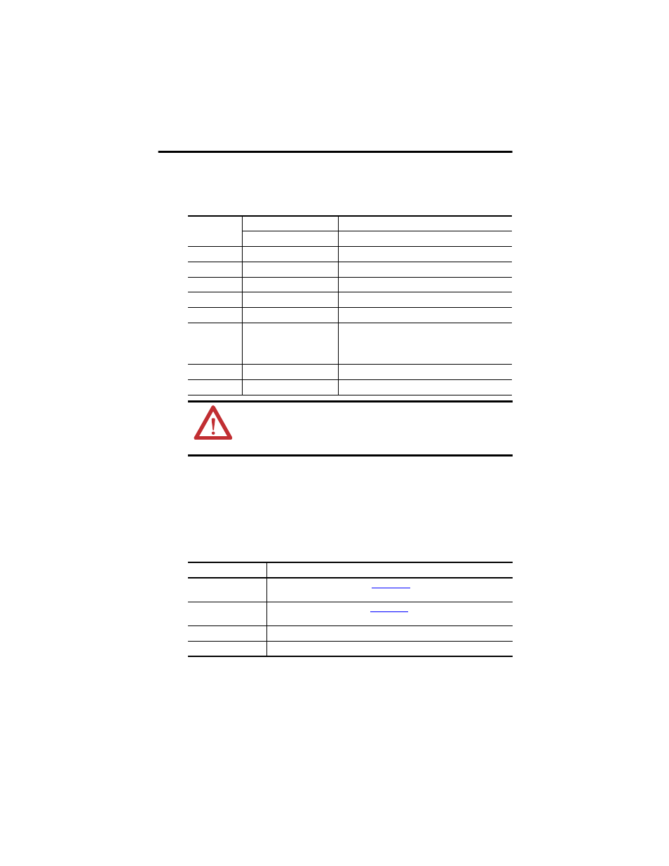
4. Set parameters for either absolute homing or torque level-to-marker homing as shown in
the table.
5. Do the following for absolute homing.
a. Use motion direct commands to slowly jog your axis to your application's home
location; do not exceed 10 mm/s (0.4 in/s).
a. Issue the Motion Direct Command (MAH) to set the home position on your axis.
6. Click the Limits tab.
7. Enter these parameters.
Parameter
Absolute Homing
Torque Level-to-Marker Homing
Value
Value
Mode Absolute
Active
Position 0,
typical
0,
typical
Offset N/A
0
mm
Sequence Immediate
Torque
Level-to-Marker
Direction N/A
Reverse
Bi-directional
Torque Level
N/A
30%, min
Greater if the system friction, force, or weight exceeds 30%
of the Continuous Force Rating at any point in the range of
motion
Speed N/A
10 mm/s
(1.97 in/s)
Return Speed
N/A
10 mm/s (0.39 in/s)
ATTENTION: Avoid excessive force while homing the electric cylinder. Do not exceed 10 mm/s (0.4 in/s)
during a home routine.
Speeds greater than 10 mm/s (0.4 in/s) can damage the electric cylinder when the piston rod reaches
the end of travel.
Parameter
Entry/Selection, with Applicable Distance Unit Settings
Hard Travel Limits
Check if hardware limits are in use. Use th
ftware to determine
the maximum stopping distance in your application to set negative and positive limits.
Soft Travel Limits
Check if software limits are in use. Use the
software to determine
the maximum stopping distance in your application to set negative and positive limits.
Maximum Positive
Enter a value that is within the piston rod mechanical travel.
Maximum Negative
Enter a value that is within the piston rod mechanical travel.