Catalog number explanation – Rockwell Automation TLAR Electric Cylinders User Manual
Page 3
TL-Series Electric Cylinders 3
Rockwell Automation Publication TLAR-IN001B-EN-P - February 2014
Catalog Number Explanation
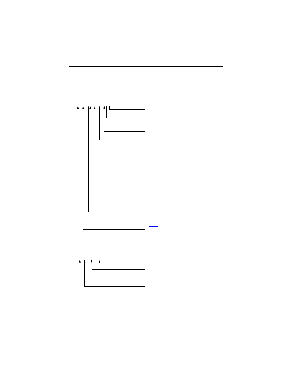
Catalog numbers consist of various characters, each identifies a specific version or option for that
component. Use the catalog numbering chart below to understand the configuration of your
actuator.
Motor Mounting
(1)
A = Axial (in-line)
Holding Brake
(1)
2 = No Brake
4 = 24V DC Brake
Feedback
(1)
B = Multi-turn, absolute 17-bit encoder, battery backed
Mechanical Drive/Screw Lead, Motor Type
B = 3.0 mm/rev (0.118 in./rev)
C = 5.0 mm/rev (0.197 in./rev)
E = 10.0 mm/rev (0.394 in./rev)
F = 12.7 mm/rev (0.50 in./rev)
H = 20.0 mm/rev (0.787 in./rev)
Rod Stroke Length
100 = 100 mm (3.94 in.)
200 = 200 mm (7.87 in.)
300 = 300 mm (11.81 in.)
400 = 400 mm (15.75 in.)
600 = 600 mm (23.62 in.)
800 = 800 mm (31.50 in.)
Actuator Frame Size
1 = 32
2 = 40
3 = 63
Voltage Class/Designator
A = 230V motors
X = Actuator cylinder replacement part (refer to Actuator Cylinders on
page 36
for ordering examples)
Actuator Type
AR = Actuator Rod
Bulletin Number
TL-Series™
(1)
This field does not apply to actuator cylinder replacement parts.
TL AR -
xx xxx x - x x A
Accessory Item Number
Accessory Type
NA = Axial (in-line) Mounting Accessory
NP = Parallel Mounting Accessory
NE = Rod-end Accessory
Actuator Type
AR = Actuator Rod
Bulletin Number
MP = MP-Series™ or TL-Series Actuator Accessory
MP AR -
xx xxxxxx