Rockwell Automation FlexPak 3000 DC Drive Version 4.3 User Manual
Page 84
B-12
FlexPak 3000 DC Drive Hardware Reference Version 4.3
Figure B.11 – Dressing Power and Control Wires
When the AC power leads must leave the ground plane of the mounting panel to make
connection to elevated device terminals, a ground wire should be run with that wire
bundle.
See figures B.13 and B.14 for typical panel electrical layouts.
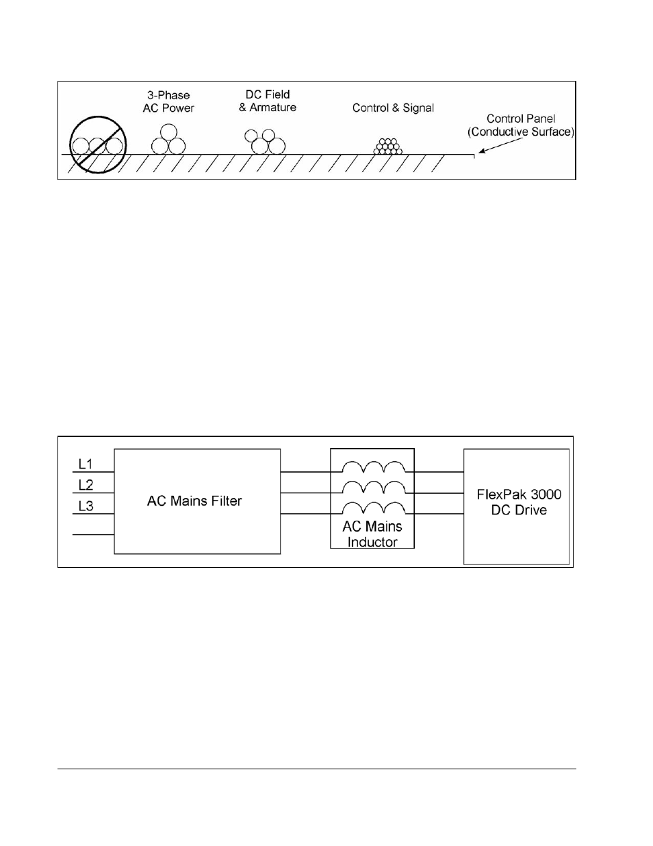
B.5.3 Wiring the AC Mains Filter
The mains filter is connected in series from the AC supply line to the AC mains
inductor to the input terminals of the drive. See figure B.12.
AC power wiring from the electrical cabinet power entry to the mains filter must be:
•
as short as possible.
•
separated from any other wiring to prevent coupling high frequency noise back to
the filtered leads.
•
run as close to the ground plane as possible.
Figure B.12 – AC Mains Filter, Inductor and FlexPak 3000 Drive Wiring
B.5.4 Wiring the AC Mains Inductor
Install the mains inductor between the mains filter and the AC power input of the
FlexPak 3000 drive as shown in figure B.12.
B.5.5 Wiring the Motor
Field and armature circuit wiring that is internal to the electrical cabinet must be:
•
Separated from all other wiring on the panel.
•
As close to the ground plane as possible. This is especially important if an
inverting fault breaker or dynamic braking circuit is part of the armature circuit.