Rockwell Automation FlexPak 3000 DC Drive Version 4.3 User Manual
Page 46
2-32
FlexPak 3000 DC Drive Hardware Reference Version 4.3
2.5.6 Wire Optional Devices to the Drive
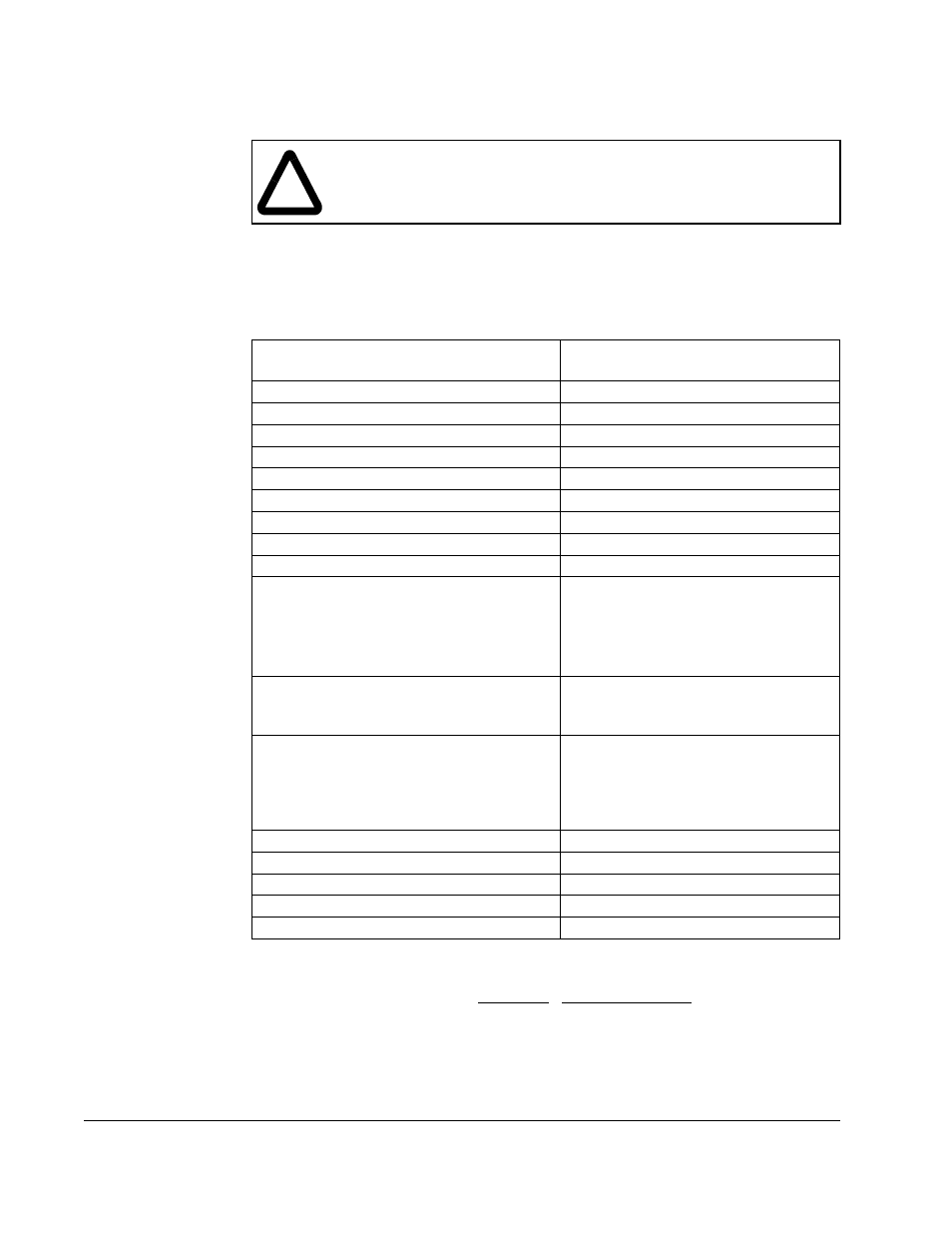
Refer to figures 2.24 and 2.25 and table 2.5 when wiring optional devices to the drive.
Size and install all wiring in accordance with the NEC and all other applicable local
codes.
!
ATTENTION:Do not route signal wiring with power wiring in the same
conduit. This might cause interference with drive operation. Route signal
wiring and power wiring in separate conduits. Failure to observe this
precaution could result in damage to, or destruction of, the equipment.
Table 2.5 – User Device Connections to the Regulator Board Terminal Strip
User Device
Regulator Board
Terminal Strip Numbers
RUN
1 (+24V) and 2
STOP
1 (+24V) and 3
JOG
1 (+24V) and 4
REV/FWD
1 (+24V) and 5
AUTO/MAN
1 (+24V) and 6
INTERLOCK
9 and 11 (+24V)
FAULT/ALARM RESET
10 and 11 (+24V)
DIGITAL INPUT 0
12 and 14 (+24V)
MOTOR THERMOSTAT
13 and 14 (+24V)
SPEED REFERENCE
POTENTIOMETER:
•
High Side (+10 ISOL)
•
Wiper (+ MAN REF)
•
Low Side (-MAN REF)
16
17
18
AUTO REFERENCE:
(+)
(-)
19
20
TACHOMETER (Analog):
1
High Range
2
Low Range
2
Common
2
1.
Analog tachometer must be rated between 18 and 200 Volts/1000 RPM. The output voltage must not
exceed 250 V for a DC tachometer or 275 RMS for AC tachometers when the motor is rotating at the
value set for the TOP SPEED parameter. To calculate the output voltage at top speed:
Tachometer Voltage at TOP SPEED = TOP SPEED x ANALOG TACH VOLTS
1000 1000
See section 3.4.7 for information on jumpers J14 and J11.
2.
When the maximum tach voltage at top speed is 62 VDC, use terminals 22 and 23 to connect the analog
tachometer. When the maximum tach voltage at top speed is 250 VDC, use terminals 21 and 23 to
connect the analog tachometer.
21
22
23
METER OUTPUT 1
24 and 25 (common)
METER OUTPUT 2
25 (common) and 26
RUNNING (Indicator)
27 and 28
ALARM (Indicator)
29 and 30
NO FAULT (Indicator)
31 and 32