Installation summary, Grounding considerations, Determine module slot location – Rockwell Automation 1756-Enxxx_Ewxxx EtherNet/IP Modules Installation Instructions User Manual
Page 14
14
Rockwell Automation Publication ENET-IN002F-EN-P - January 2014
Chapter 1 Install a 1756 EtherNet/IP Communication Module
Installation Summary
Follow these steps to install a communication module in a 1756 ControlLogix
chassis.
1.
Set the Network IP Address on a Module
2.
Determine Module Slot Location
3.
4.
Connect the Module to an EtherNet/IP Network via an RJ45
Connection
or
Connect the Module to an EtherNet/IP Network via a Fiber Connector
5.
6.
Connect to the Module via the USB Port
7.
. - Optional
8.
Apply Chassis Power and Check Status Indicators
9.
Install or Remove the Module Under Power
. - Optional
Grounding Considerations
The grounding and bonding must be of equal potential between all devices in the
communication coverage area.
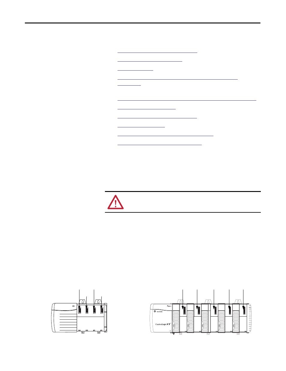
Determine Module Slot
Location
Install the communication module in any slot in a ControlLogix or
ControlLogix-XT™ chassis. You can install multiple communication modules in
the same chassis.
This example shows chassis slot numbering in a 4-slot ControlLogix chassis and a
5-slot ControlLogix-XT chassis. Slot 0 is the first slot and is always the leftmost
slot in the chassis.
ATTENTION: If this equipment is used in a manner not specified by the
manufacturer, the protection provided by the equipment may be impaired.
20806
Slot 2
Slot 0
Slot 1
Slot 3
ControlLogix Chassis
ControlLogix-XT Chassis
31896
Slot 0
Slot 4
Slot 1
Slot 2
Slot 3