Module indicators, Module status (ms) indicator – Rockwell Automation 1440-RMA00-04RC XM-440 Master Relay Module User Manual
Page 38
Rockwell Automation Publication GMSI10-UM009D-EN-P - June 2011
38 Installing the XM-440 Master Relay Module
Module Indicators
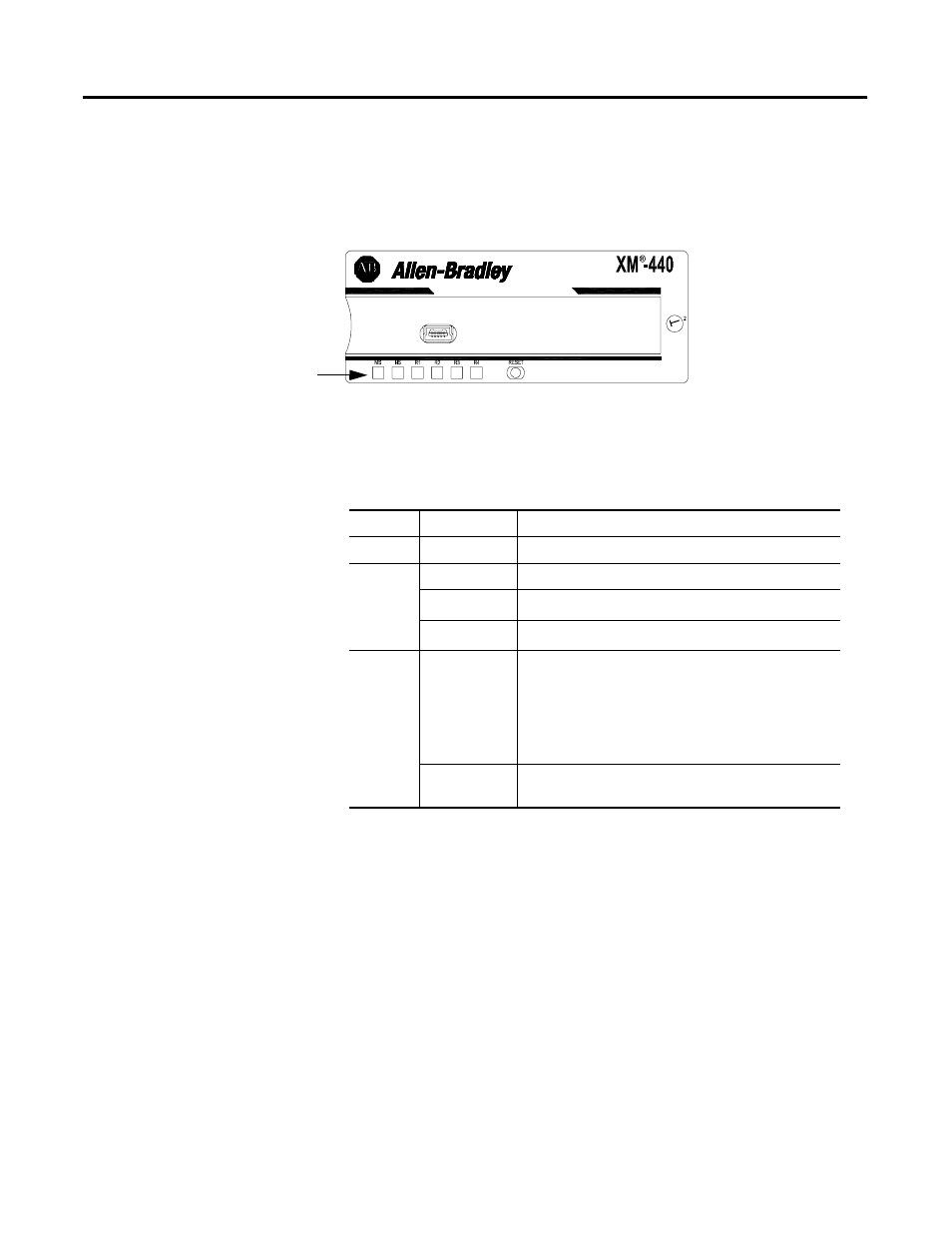
The XM-440 has six LED indicators, which include a module status (MS)
indicator, a network status (NS) indicator, and a status indicator for each Relay
(four in all). The LED indicators are located on top of the module.
Figure 2.16 LED Indicators
The following tables describe the states of the LED status indicators.
Module Status (MS) Indicator
1
Program Mode - Typically this occurs when the module configuration settings are being updated with the XM
Serial Configuration Utility. The module closes I/O connections with the XM measurement modules in its
scanlist. The alarm monitoring is stopped, the relay outputs are deactivated unless they are latched.
Configuration parameters can be read, updated and downloaded to the XM module.
2
Run Mode - The module establishes I/O connections with the XM measurement modules in its scanlist, collects
their alarm status, and controls its own relay outputs accordingly.
MASTER RELAY
1440-RMA00-04RC
Module Indicators
Color
State
Description
No color
Off
No power applied to the module.
Green
Flashing Red
Module performing power-up self test.
Flashing
Module operating in Program Mode
1
.
Solid
Module operating in Run Mode
2
.
Red
Flashing
• Application firmware is invalid or not loaded.
Download firmware to the module.
• Firmware download is currently in progress.
• Module is configured incorrectly. Verify that each
slave’s module type is correct.
Solid
An unrecoverable fault has occurred. The module may
need to be repaired or replaced.