Signal wiring – Rockwell Automation T6200 Compressor Anti-Surge and Capacity Controller User Manual
Page 32
Hardware Installation/Maintenance
3-10
Signal Wiring
Individually shielded wires are not required (except for frequency inputs). Twisted pairs and overall
cable shields are recommended. Each multipair cable should contain a few pairs of spare wires. Shields
and unused conductors should be terminated to ground at Controller end only. Refer to appropriate
Wiring and Jumper Placement.
The following general guidelines apply to all signal wiring discussed in the following paragraphs.
Wire size range for the terminal panel is 26-16 AWG stranded; recommended wire size range
is 18-14 AWG.
Wire size range for the remote I/O terminal is 26-14 AWG stranded; recommended wire size
range is 18-14 AWG.
All wiring should be multi-stranded annealed copper with insulation that meets the
requirements of all applicable electrical codes.
Keep all wire runs as short and direct as possible. Long wire runs are vulnerable to picking up
stray electrical noise. Use care when running signal wiring near to or crossing conduit or
wiring that supplies power to motors, solenoids, lighting, horns, bells, etc.
Avoid bringing signal wiring into junction boxes which contain other wiring.
AC power wiring should be run in a separate conduit from the signal wiring.
The stripped portion of the wires should be 5/16” (8 mm) long.
Wires should be inserted in the clamp type terminals until they touch the internal stops. The
terminal screw should be tightened while holding the wire in place. Check for proper clamp
pressure with a gentle tug on the wire.
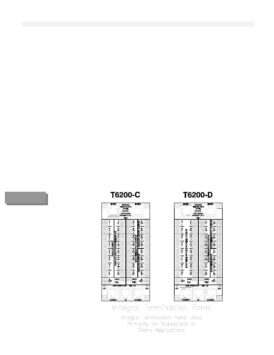
FIGURE 3-8
Integral
Termination
Panels