Analog current inputs, Analog current outputs – Rockwell Automation T6200 Compressor Anti-Surge and Capacity Controller User Manual
Page 16
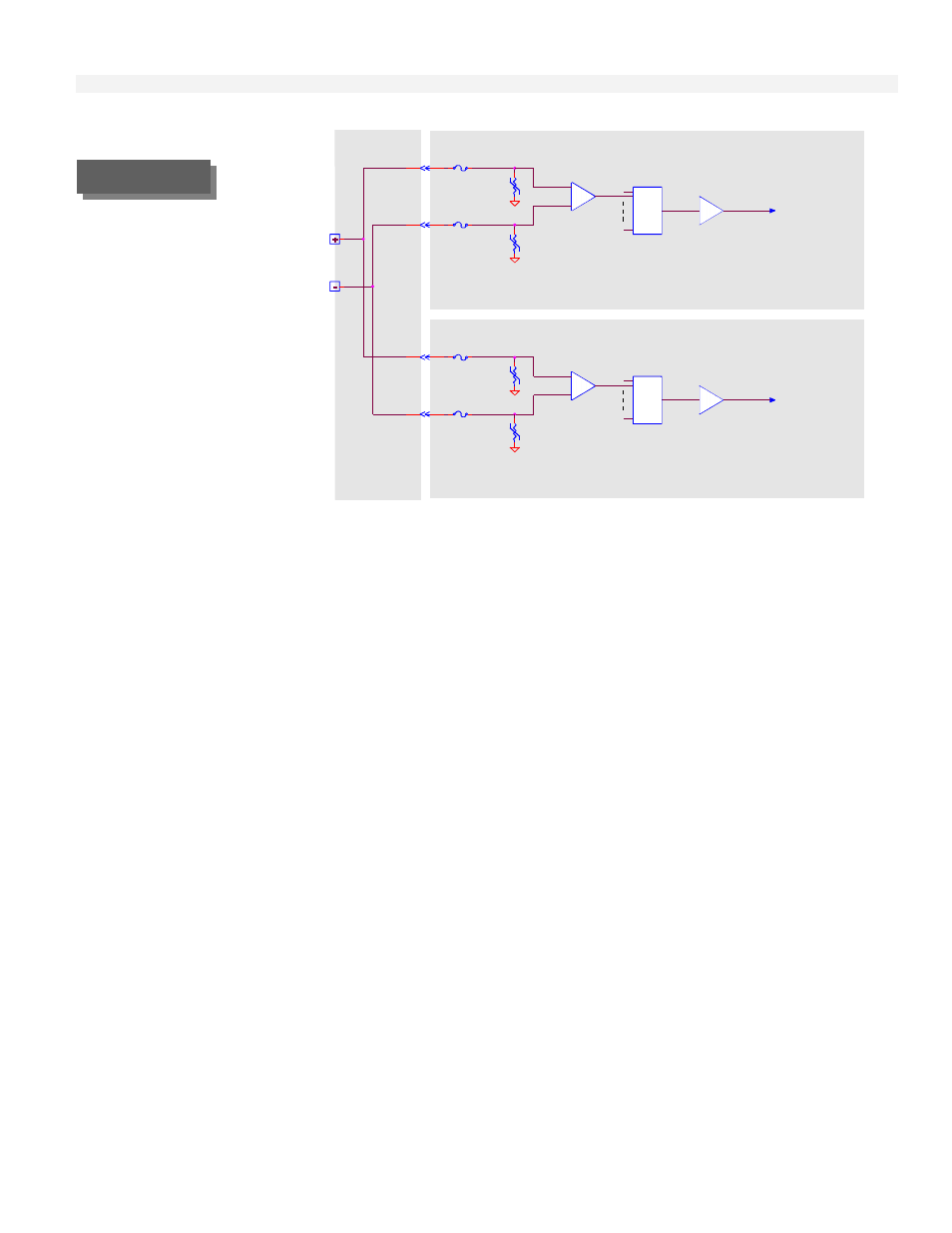
Input/Output Circuit Description
2-4
Gain Amplifier
100V
1A
200 Volt
To ADC
Switch
Termination
Panel
100V
1A
Gain Amplifier
Backup Control Board
Analog
Voltage
Input
200 Volt
1A
Common-mode
100V
Analog
Switch
To ADC
Primary Control Board
Amplifier
Programmable
1A
Amplifier
Analog
100V
Programmable
Common-mode
Analog Current Inputs
The current input is similar to the voltage input with 250 ohm resistor across the amplifier inputs. Field
changeable jumpers are used to select between voltage or current input. The maximum continuous input
current is 20 mA and 40 mA momentary. Refer to Figure 2-2. Also the gain is increased in the PGA by a
factor of two when a backup control board is present, to compensate for the decrease in voltage that the
additional 250 ohm resistor will cause.
When an isolated two-wire 4 to 20 milliampere transmitter is used, the circuit shown in Figure 2-3 may be
used. In this configuration a separate internal +24 volt voltage regulator is used for each transmitter. Each
voltage regulator has thermal, reverse voltage, and short-circuit protection. In this arrangement, one end
of the 250 ohm resistor is connected to circuit common. The two-wire 4-20 mA represents the standard
analog input jumper selection.
Analog Current Outputs
The T6200 Controller can be configured from four to eight current outputs. The current output will source
from 0 to 20 milliamperes to the user's receiver (load). The receiver must share the same circuit common
as the T6200 Controller. The maximum receiver resistance is 1000 ohms.
In reference to Figure 2-4, the digital to analog converter (DAC) receives a digital value from the
microprocessor and converts it to an analog voltage. The voltage to the current converter, combined with
transistor Q1 and the 50 ohm resistor, converts the voltage to a current signal.
The output of the primary and backup control boards are connected together on the Controller termination
panel. The output is only enabled in the active control board. The diode is used to block the current from
the active control board.
Analog Voltage
Input
FIGURE 2-1