Rockwell Automation T6200 Compressor Anti-Surge and Capacity Controller User Manual
Page 194
Modbus Interface – RS-232/RS-485
B-4
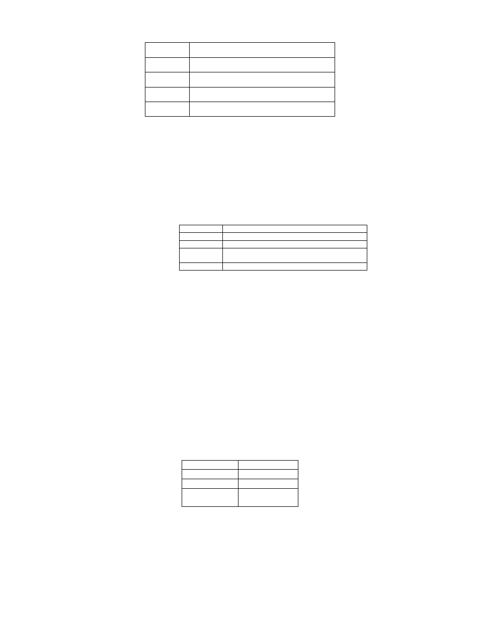
Maximum number (1..2000) of coils or inputs to poll
with one message.
Maximum number (1...125) of registers to poll with
one message.
OFFSET
Difference between point number and on-the-wire
address. (Modicon specifies 1)
PRIORITY
Unit priority scan. Default priority is 1. Place only a
small number of high priority points at priority zero.
RETRY
Retry count and optional interval. Interval defines the
expected response time of the unit.
Table 1 Polling Parameter Values
The default polling parameters are:
“@ 3
GAP 0 0 MAX 16 10 OFFSET 1
RETRY 10 / 1 PRIORITY 1”
The lowest numbered priorities take precedence over higher numbered priorities. In order to
insure that all points cannot possibly be scanned as frequently as specified, the priority scan is
cascaded: Whenever a priority level is completed, at lease one poll will be performed at the next
level even if it is already time to poll a higher priority block.
UNIT {1..247}[=
{[
{“+” | “-“} [“:” [[“-“]
[H [, L[, h[, I]]]]
{-15.. 16, 32}
Table 2 UNIT Directive
The UNIT directive introduces each MODBUS unit. Units may be numbered from one to 247
according to the MODBUS specification. The optional
reporting of off-line unit alarms. Most of the polling parameters,
MODBUS masters. The specific syntax depends upon the
The
port. Once an address is specified, tags will be assigned successive addresses until a new starting
address is specified. Multiple tags may not be assigned to a single address. Use a comma to
separate point tag names only if a break in polling messages is required there; otherwise separate
tag names with a space. The values of tags can be shared with the reserve controller over the
backup link: prefix the tag name with ‘&’ to include it in backup data sent from the active to the
reserve controller. Subsequent tags will also be sent to backup until a comma delimiter or a new
address.
MODBUS
discretes which can only be assigned to U-32 Boolean tags. Input and holding registers are sixteen
or thirty-two bit integers which can be assigned to any data type. If no data type is otherwise
specified for a controller tag, it defaults to the type of the remote point.
00001..09999
1
Coils
10001..19999 Discrete
inputs
30001..39999 Input
registers
40001..49999 Holding
registers
Table
3
1
Since the first digit of
zeros may be omitted. For example “00001” may be written “01” for the first coil and “40001”
may be written “41” for the first holding register.