Rockwell Automation T6200 Compressor Anti-Surge and Capacity Controller User Manual
Page 155
Configuration
8-35
T6200 – Variable, Alarm & Tuning Settings
Enter/verify all settings & make sure that they comply with the requirements of your application.
Ensure that these settings are defined in the Straton for MICON FB Program and Variable List.
Setting apply to each compression stage!
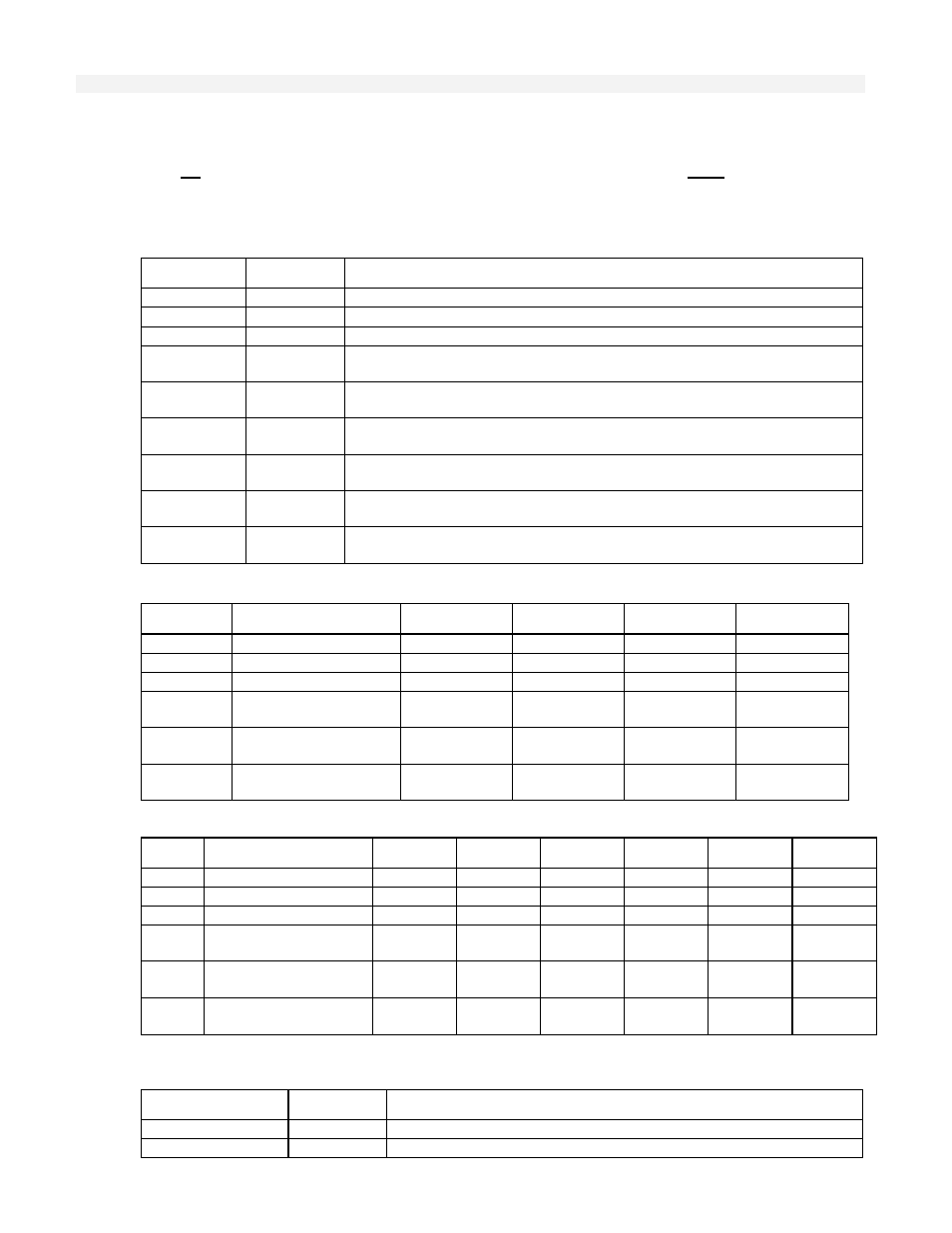
Table T1. - Anti-Surge Variables – Initial Settings
Name Init.
Value
Description
K
Co-Efficient=
(R2/R1)*(Za/Zs)*(1/A**2) – Enter K value from M/C Tool
M_pr_FBset
M_pr Fallback Value (k-1/K*Pe), FB on Ps|Ts Fail – Verify with M/C Tool
SAFEh
SAFE ‘h’ Fallback Value if Suction Press XTMR fails – Verify with M/C Tool
A
Flow Co-Efficient (for Q display) – from M/C Tool
Zs
Inlet Compressibility (indication, used in K and Q calculations)
Zd
Discharge Compressibility (indication)
MW_Set
Molecular Weight Entry (for display only, not used in surge calculations)
R1
R1 Gas Constant for Q and K calculations (EU=10.73, MU= 0.08478)
R2
R2 Gas Constant for Hp and K calculations (EU= 1545, MU= 847.80)
Table T2. - Anti-Surge and Incipient Surge Fallback (FB) Alarm Values and Limits
Name Description
Value_Max
Limit_Max
Limit_Min
Value_Min
Ps
Suction
Pressure
Pd
Discharge
Pressure
Ts
Suction Temp
Td
Discharge Temp
h
Flow ‘h’ (Suct or
Disch)
Incip_SG
SurgeGard Input
Table T3. - Anti-Surge and Incipient Surge Process (XM) Alarm Limits for Compressor
Name Description Max HH H
L LL Min
Ps
Suction Pressure
Pd
Discharge Pressure
Ts
Suction Temp
Td
Discharge Temp
h
Flow ‘h’ (Suct or
Disch)
Incip_
SurgeGard Input
Recommended Alarm Levels: Ps=High-Low-Min; Pd=High-Low; Ts=High; Td=High; h=Low-Min; Incip_SG= High
Table T4. - Anti-Surge Op Tracking and Surge Spike Settings
Name Init.
Value
Description
SP_Hv_Thr
Setpoint Hover (Op Tracking) Enable % above SCL-Surge Control Line
SP_Hv_Mgn
Setpoint Hover (Op Tracking) Margin (track % to Op Point)