Figure, Figure b.8, Fanmaster diagrams b-9 – Rockwell Automation FANM FanMaster Energy Saving Package User Manual
Page 83
FanMaster Diagrams
B-9
Allen-Bradley® FanMaster™ Energy Saving Package Installation Manual -
Publication FANM-IN001B-EN-P – December, 2009 PN-65329
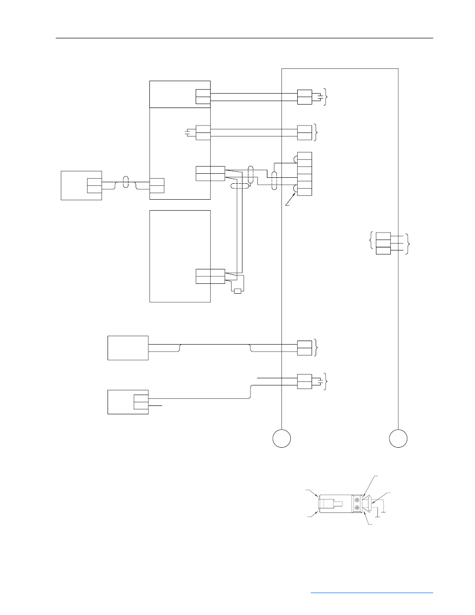
Figure B.8
Interconnect Diagram for PowerFlex 400 Drive - Sheet 1
FanMaster
TB2
TB3
TB1
TB2
TB2
Supply Fan Drive
PowerFlex 400
Drive TB
R4
R5
Drive Running
RS-485
RJ45
B
A
AK-U0-RJ45-TB2P - RJ45 to TB Adapter
(Typ. both Drives)
See adapter detail below
Signal = 120V AC
Signal = 4-20 mA
+
–
Optional Position
Command to Damper
Drive TB
15
14
A.O. 1
A.O. Com
PowerFlex 400
RS-485
RJ45
B
A
120 Ohm
Termination Resistor
(See Note 7)
Signal = RS-485
Signal = 24V DC
Damper Position
Switch (In Econ. Mode)
BAS Outside Air
Damper Override Control
Black
Red
Line
Common
Signal = Customer Selected
Customer Supplied Line
Customer Supplied Nuetral
119
120
100
105
135
N
Fan Running Input
120V AC Input
L
N
G
Factory Installed Jumpers
Customer
Supplied
120V AC,
50/60 Hz
Power
Econ. Mode Switch +24V DC
Input Signal for Econ. Mode Switch
BAS Damper Override
Control Output
A
A
Notes:
1. All power, I/O and signal wire is customer supplied.
2. Non-shielded wires to be Belden No. 3105A or equal.
3. Shielded cable to be a Belden No. 3106A or equal.
4. On PowerFlex 400, style A, NEMA/UL Type 3R, 4 & 12 drives, jumper TB1-35
in the drive enclosure to drive signal terminal 8.
5. CR4 in FanMaster to be 700-HK32A24 for 24V AC or 700-HK32A1 for
120V AC BAS Start Signal.
6. For drives with Full Feature Bypass only, connect terminals 61 and 162 on
FanMaster TB2 to terminals 34 and 36 on TB1 in the enclosure as shown.
7. It the optional return fan is not used, move the termination resistor to the
supply fan terminals A and B.
8. When using a PF400 drive with a full feature bypass and speed pot, add new
switch contact, part number 800F-X10, to the Hand Off Auto switch in the
“Auto” position. The switch snaps into place on the second switch level on the
right side of the switch as viewed from the rear. Connect a wire from PF400
terminal 11 to the top of the switch. Connect a wire from the bottom of the switch
to PF400 terminal 8. Verify that the switch contact closes when “Auto” is selected.
(See Note 4)
Return Fan Drive
(Optional)
(See Note 4)
To Sheet 2
To Sheet 2
B (Pin 4)
A (Pin 5)
Resistor
Adapter Detail
Shown with 120 Ohm
Terminating Resistor
Pin 1
Pin 8
TB2
161
162
BAS Start CR4-1
(See Notes 5 and 6)
Enclosure
TB1
34
36
Bypass Enable
CGND
SHLD
COM
B
A
TERM