Rockwell Automation FANM FanMaster Energy Saving Package User Manual
Page 29
FanMaster Installation
2-11
Allen-Bradley® FanMaster™ Energy Saving Package Installation Manual -
Publication FANM-IN001B-EN-P – December, 2009 PN-65329
Wire the FanMaster and Drive (if Installed)
Refer to the
contained in Appendix B for wiring and
connection details.
1. For permanent installations, determine where conduit will be routed and
prepare the FanMaster enclosure for conduit connections.
–
For NEMA/UL Type 1 enclosures, remove the metal plugs in the
pre-located openings in the enclosure for conduit connections.
–
For NEMA/UL Type 4 enclosures, drill the desired openings in the
enclosure to accommodate conduit connections.
2. Open the FanMaster enclosure and verify that circuit breaker 1 (CB1) is
in the “off” position.
3. Route the power wires through the appropriate conduit (if used) and
connect to terminals L, N and G on terminal block 1 (TB1). Refer to
Wiring Specifications on page 2-2
for power wire size.
!
ATTENTION: Do not route signal and control wiring with
power wiring in the same conduit. This can cause interference
with operation. Failure to observe this precaution could result in
damage to, or destruction of, the equipment.
!
ATTENTION: Protect the contents of the enclosure from metal
chips and other debris while removing the conduit opening plugs.
Failure to observe this precaution could result in damage to, or
destruction of, the equipment.
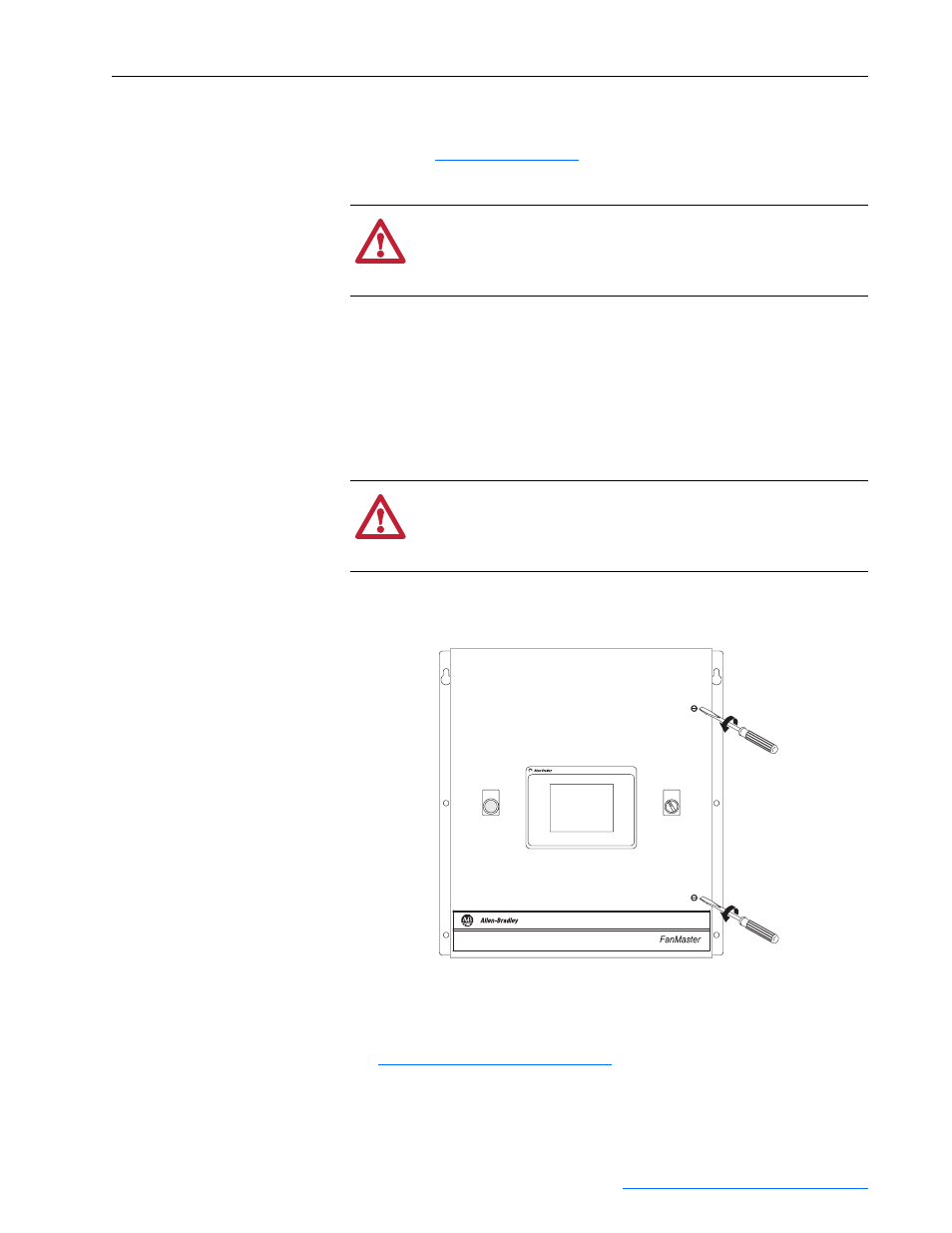
FANMASTER
FAULTED
FANMASTER
OVERRIDE
OFF ON
PanelView C600
NEMA/UL Type 1 Enclosure Shown