Rockwell Automation GV3000/SE, VTAC 7 Super Remote Meter Interface Board M/N 2SI3000 M/N 2SI3000E User Manual
Page 42
3-28
Super Remote Meter Interface (RMI) Board
Step 4.
Install the RMI Board in the Keypad Bracket
Step 4.1 Remove the RMI board from its anti-static wrapper and verify that the
jumper settings are correct. Refer to figure 2.1 for jumper locations and
appendix A for jumper settings.
Step 4.2 Align the key on the Regulator board’s 34-conductor ribbon cable connector
with the slot in the RMI board’s connector. Press the ribbon cable connector
in until it locks into position.
Step 4.3 Align the RMI board on the four mounting tabs on the keypad bracket. Make
sure that the ribbon cable is not pinched between the keypad bracket and
the RMI board.
Step 4.4 Fasten the RMI board to the right side of the keypad bracket using the two
metal M3 screws and lock washers for proper grounding. Fasten the left
side using the two 6-32 screws and lock washers for proper grounding.
Important: You must use the lock washers to properly ground the RMI board. Improper
grounding of the RMI board can result in erratic operation of the drive.
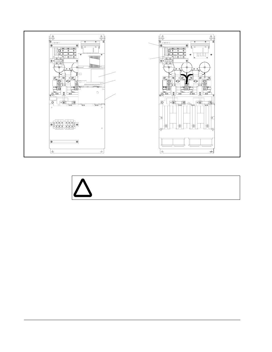
Figure 3.14 – Drive Components and Locations (50 to 100 HP @ 460 VAC)
45
47
47
45
Keypad
Regulator
Board
Power Module
Interface Board
DC Bus
Measuring Points
+
–
!
ATTENTION: The RMI board contains components that are
static-sensitive. An anti-static wrist band should be worn by any person
who touches the board’s components, connectors, or wiring. Failure to
observe this precaution could result in damage to the RMI board.