Rockwell Automation GV3000/SE, VTAC 7 Super Remote Meter Interface Board M/N 2SI3000 M/N 2SI3000E User Manual
Page 38
3-24
Super Remote Meter Interface (RMI) Board
Step 4.5 Align the key on the Regulator board’s 34-conductor ribbon cable connector
with the slot in the RMI board’s connector. Press the ribbon cable connector
in until it locks into position.
Step 4.6 Align the RMI board on the four mounting tabs on the keypad bracket. Make
sure that the ribbon cable is not pinched between the keypad bracket and
the RMI board.
Step 4.7 Fasten the RMI board to the right side of the keypad bracket using the two
metal M3 screws and lock washers for proper grounding. Fasten the left
side using the two 6-32 screws and lock washers for proper grounding.
Important: You must use the lock washers to properly ground the RMI board. Improper
grounding of the RMI board can result in erratic operation of the drive.
Step 4.8 Realign the 26-conductor ribbon cable connector with the Power Supply
board connector inside the slot in the keypad support bracket. Carefully
press the ribbon cable connector in until the retaining clips lock it into place.
Step 5.
Reinstall the Keypad Bracket in the Drive
Step 5.1 Reconnect the keypad bracket to the keypad support bracket by inserting
the mounting tabs into the slots in the keypad support bracket and
tightening the thumb screw.
Step 5.2 Connect the RMI wiring to the appropriate RMI terminals for your
application. Route the wire through the left-most wire-routing hole at the
bottom of the drive. Refer to section 3.9 for terminal identification.
Step 5.3 Reconnect any wiring that was removed from the Regulator board terminal
strip. Refer to the terminal connections documented in step 3.1 or to the
appropriate instruction manuals for the devices being used.
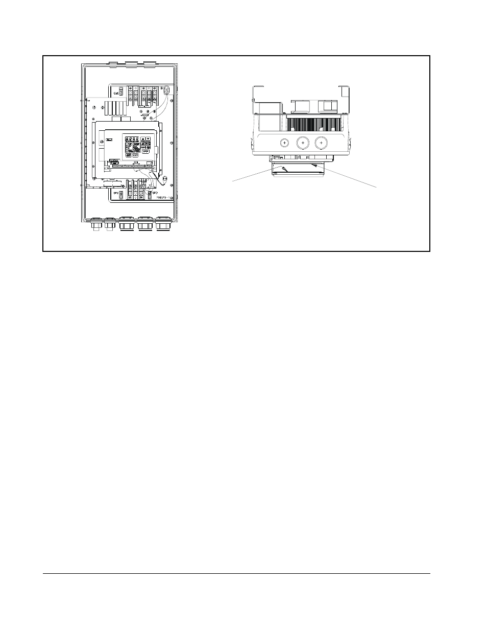
Figure 3.13 – RMI Board Location in 25 to 60 HP @ 460 VAC Drives
Regulator Board
RMI Board
Front View
Top View