Rockwell Automation GV3000/SE, VTAC 7 Super Remote Meter Interface Board M/N 2SI3000 M/N 2SI3000E User Manual
Page 23
Installation
3-9
Step 2.
Verify That the DC Bus Capacitors are Discharged
Step 2.1 Use a voltmeter to verify that there is no voltage at the drive’s AC input
power terminals (R/L1, S/L2, T/L3).
Step 2.2 Ensure that the DC bus capacitors are discharged. To check
DC bus potential:
a. Stand on a non-conductive surface and wear insulated gloves.
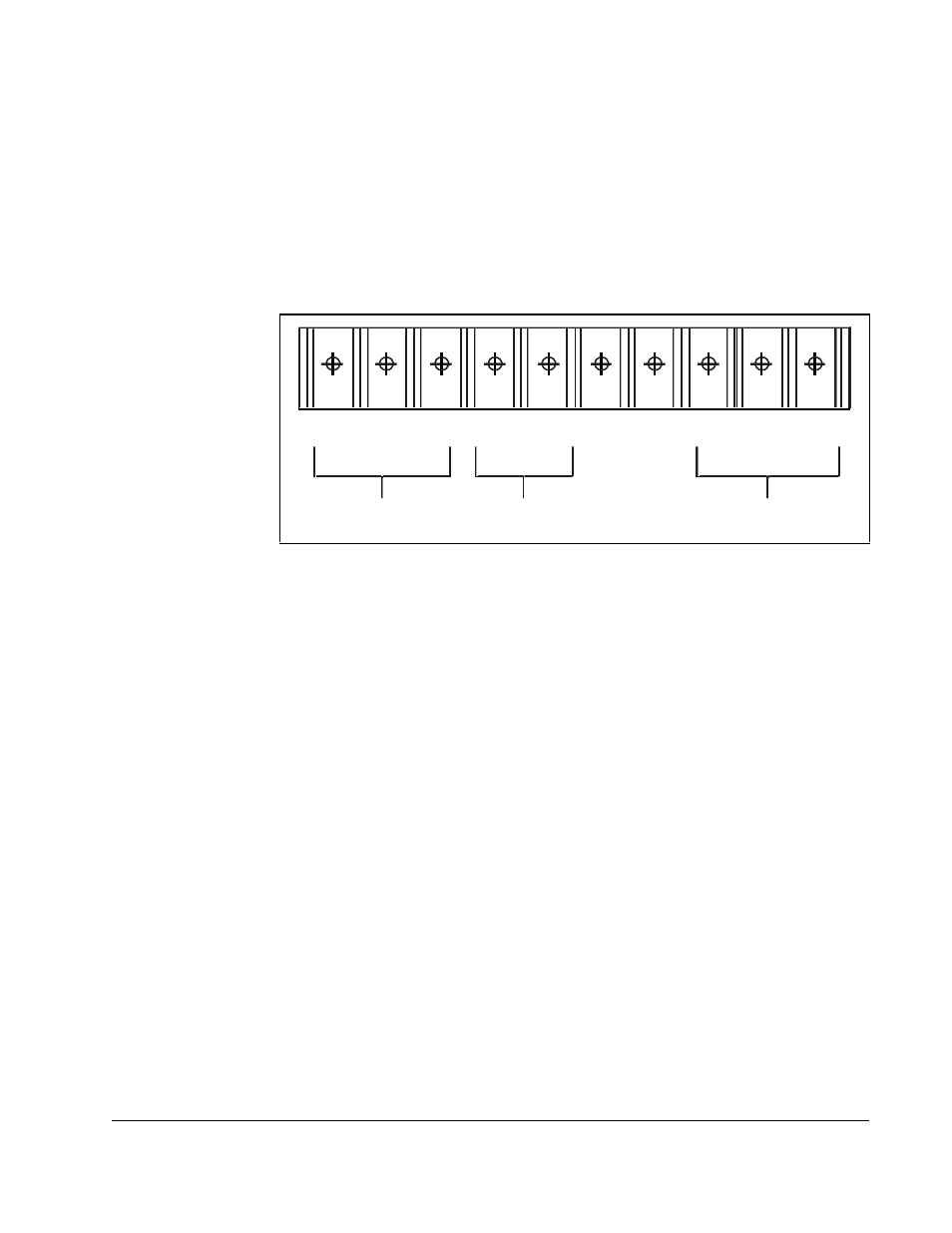
b. Use a voltmeter to measure the DC bus potential at the DC bus power
terminals shown in figure 3.3.
Step 3.
Remove the Keypad Bracket from the Drive
Step 3.1 Record connections to the Regulator board terminal strip if they must be
disconnected to remove the keypad bracket.
Step 3.2 Loosen the thumb screw on the left side of the keypad bracket. Hold the
bracket on the left and lift the bracket up and to the left to separate it from
the keypad support bracket.
Important: The keypad support bracket is connected to the drive by wiring. Do not lift
the bracket out completely, because this can damage or pull out wiring.
Tie up or support the bracket to prevent damage to the wiring.
Step 3.3 Spread the retaining clips on the 26-conductor Regulator board ribbon
cable connector to disconnect it from the Current Feedback board. The
Current Feedback board is located on the right below the keypad.
Figure 3.3 – DC Bus Voltage Terminals (7.5 to 10HP @ 460VAC)
W/T3
V/T2
U /T1
+
S/L2
1 0V
1 0 COM
Motor Leads
AC Power
Input Leads
DC Bus
Volts
R/L1
T/L3
–
+
–