Hapter, Mechanical/electrical description, 1 status led – Rockwell Automation GV3000/SE, VTAC 7 Super Remote Meter Interface Board M/N 2SI3000 M/N 2SI3000E User Manual
Page 11
Mechanical/Electrical Description
2-1
C
HAPTER
2
Mechanical/Electrical Description
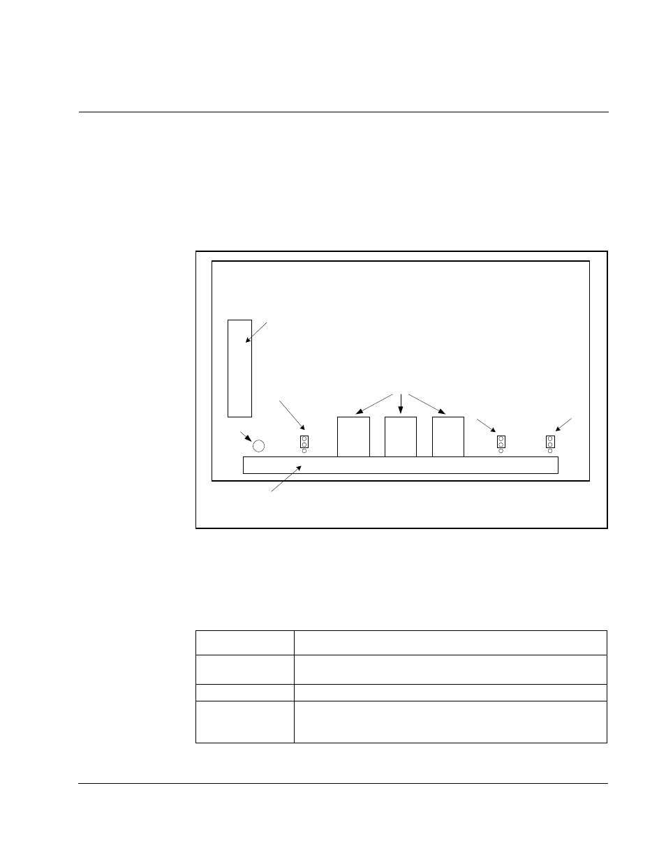
The optional RMI board is a printed circuit assembly that mounts inside the drive. It
connects to the Regulator board through a flexible ribbon cable and is powered by the
drive power supply. Refer to figure 2.1 for the RMI board layout. This figure also shows
the factory-set jumper positions.
2.1
Status LED
The green LED on the RMI board indicates the status of the RMI board and the
communications link between the RMI board and the drive.
Figure 2.1 – RMI Board
5HJXODWRU %RDUG 5LEERQ
&DEOH &RQQHFWRU
6WDWXV /('
2.
,17
(;7
'LJLWDO 2XWSXWV 6XSSO\
'HIDXOW ,QWHUQDO 9
5HOD\V
$QDORJ ,QSXW
'HIDXOW 9
$QDORJ 2XWSXW
'HIDXOW 9
9 ,1
& ,1
9 287
& 287
;
;
7HUPLQDO 6WULS
01 6, ERDUG SURYLGHV VFUHZ WHUPLQDOV 1RW LQWHQGHG IRU XVH LQ *96( %RRNVKHOI GULYHV
01 6,( ERDUG SURYLGHV VSULQJORDGHG WHUPLQDOV
If the LED is …
It indicates that …
On
Power-up diagnostics are complete and no fault has been
detected.
Flashing
The RMI board and the drive are communicating.
Off
The drive is not powered up or a fault has been detected on the
RMI board. See chapter 5 for a list of fault codes. (Note that the
LED will be off during a reset and during power up.)