J1f1 – Rockwell Automation 6180 Processor Board (for 6180 Industrial Computers) User Manual
Page 16
2–5
Processor Board
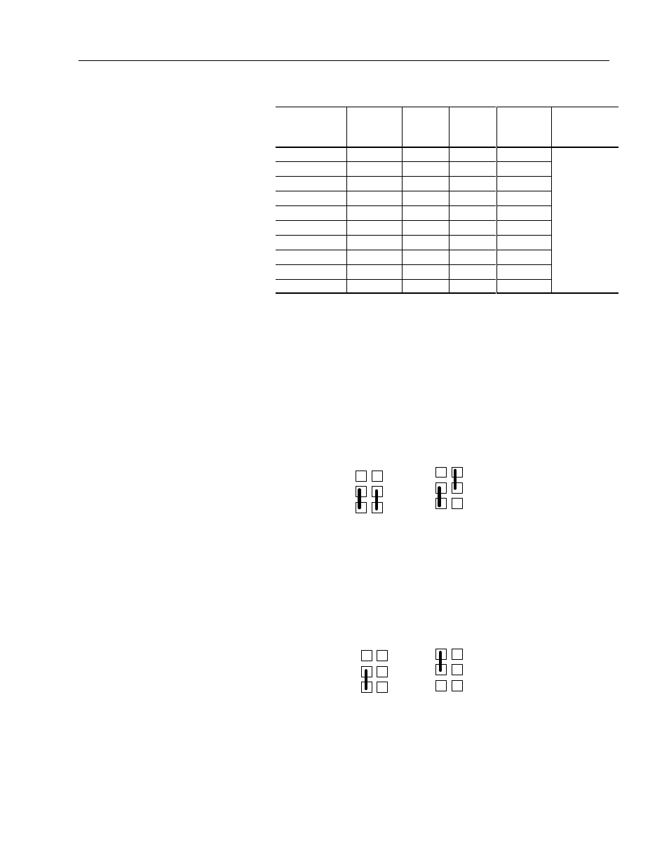
CPU/System Speed Settings
CPU Frequency
(MHz)
Host Bus
Frequency
(MHz)
Jumper
J7K1-C
Jumper
K7K1-D
CPU Clock
Multiplier
Jumper
J7K1-B
200
66
1-2, 5-6
1-2, 5-6
3
166
66
1-2, 5-6
2-3, 5-6
2.5
150
60
2-3, 4-5
2-3, 5-6
2.5
133
66
1-2, 5-6
2-3, 4-5
2.5
The STD/VRE
setting
120
60
2-3, 4-5
2-3, 4-5
2
setting
depends on
100
66
1-2, 5-6
1-2, 4-5
2
depends on
4-5 for STD,
90
60
2-3, 4-5
1-2, 4-5
1.5
4-5 for STD,
5-6 for VRE
75
50
2-3, 5-6
1-2, 4-5
1.5
5-6 for VRE
Reserved
-
2-3, 5-6
1-2, 5-6
Reserved
-
2-3, 4-5
1-2, 5-6
BIOS Recovery (Jumper J1F1 / Pins 1,2,3)
It is unlikely that a BIOS Flash Upgrade process would be
interrupted. However, if an interruption occurs that prevents the
upgrade from continuing, you may need to use the BIOS recovery.
Moving the jumper from pins 1-2 (Normal Operation) to pins 2-3
(Recovery) and then turning the system on loads the BIOS upgrade
from a diskette in the floppy drive. After recovery, the upgrade
process can be continued.
1
3
6
4
J1F1
Recovery Disabled
1
3
6
4
J1F1
Recovery Enabled
Clear CMOS (Jumper J7K1-A / Pins 4,5,6)
Moving the jumper from pins 4-5 (Keep) to pins 5-6 (Clear) and then
turning the system on, resets the CMOS settings to default
values.
1
3
6
4
A
Keep CMOS
1
3
6
4
A
Clear CMOS
After the system indicates “NVRAM Cleared by Jumper”, turn the
system off and return the jumper to the 4-5 position.