F defining variables in the configuration task, Appendix f, Defining variables in the configuration task – Rockwell Automation 57C421B Pulsetach Input Module/DCS 5000/AutoMax User Manual
Page 61: Local i/o definition, 32ćbitregister reference, Processor module pulsetach module, Sample module in a local rack
FĆ1
Appendix F
Defining Variables in the
Configuration Task
This section describes how to configure the module when it is being used in a
system with the V2.1 or earlier Programming Executive software. See instruction
manual JĆ3649 for more information on the configuration task. For later versions
of the Programming Executive software, you need to use the software forms in
the Programming Executive Variable Configurator Screens.
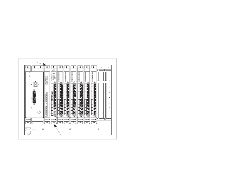
Local I/O Definition
The statements below are used to configure modules in a local rack in the
configuration task. See the figure below for an example.
1
0
2
3
4
C1
5
6
7
C2
8
9
10
11
C3
12
13
14
15
C4
B
C
D E
F
G
1
2
3
6
7
8
B
CD EFG
1
2
3
6
7
8
OK
275 W
POWER
SUPPLY
1
0
2
3
4
C1
5
6
7
C2
8
9
10
11
C3
12
13
14
15
C4
B
C
D E
F
G
1
2
3
6
7
8
1
0
2
3
4
C1
5
6
7
C2
8
9
10
11
C3
12
13
14
15
C4
B
C
D E
F
G
1
2
3
6
7
8
1
0
2
3
4
C1
5
6
7
C2
8
9
10
11
C3
12
13
14
15
C4
B
C
D E
F
G
1
2
3
6
7
8
1
0
2
3
4
C1
5
6
7
C2
8
9
10
11
C3
12
13
14
15
C4
B
C
D E
F
G
1
2
3
6
7
8
1
0
2
3
4
C1
5
6
7
C2
8
9
10
11
C3
12
13
14
15
C4
B
C
D E
F
G
1
2
3
6
7
8
120V
LINK
GND
L2
L1
FUSE
BATTERY
BACKĆUP
POWER ON
P S READY
SYSTEM READY
BLOWN FUSE
MEMORY
SET UP
PROGRAM
57491
Processor Module
Pulsetach Module
PROTECT
A
NC
B
Z
A+
FG
A-
B+
FG
B-
Z+
FG
Z-
B
C
D E
F
G
1
2
3
6
7
8
FG
Sample Module in a Local Rack
32ĆBitRegister Reference
Use the following method to reference 32 bits as a single register value. The
counter and the comparator may be referenced this way. One statement is
required in the configuration task for each variable. The symbolic name of the
register should be as descriptive as possible:
nnnnn
IODEF SYMBOLIC_NAME![ SLOT=s, REGISTER=r]